ES3J Ver la hoja de datos (PDF) - LiteOn Technology
Número de pieza
componentes Descripción
Fabricante
ES3J Datasheet PDF : 2 Pages
| |||
LITE ON POWER
SEMICONDUCTOR
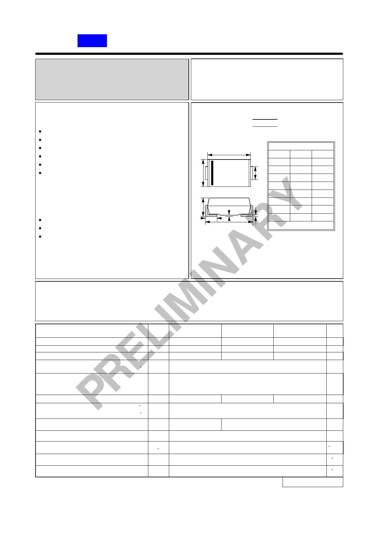
SURFACE MOUNT
SUPER FAST RECTIFIERS
ES3J thru ES3M
REVERSE VOLTAGE - 600 to 1000 Volts
FORWARD CURRENT - 3.0 Amperes
FEATURES
SMC
Glass passivated chip
Super fast switching for high efficiency
For surface mounted applications
Low forward voltage drop and high current capability
SMC
A
DIM. MIN. MAX.
Low reverse leakage current
A
6.60 7.11
Plastic material has UL flammability classification
B
C
B
5.59 6.22
94V-0
C
2.92 3.18
D
0.15 0.31
MECHANICAL DATA
Y Case : Molded plastic
Polarity : Color band denotes cathode
Weight : 0.007 ounces, 0.21 grams
E
7.75 8.13
F
0.05 0.20
G
G
2.01 2.62
H
F
D
H
0.76 1.52
E
All Dimensions in millimeter
INAR MAXIMUM RATINGS AND ELECTRICAL CHARACTERISTICS
Ratings at 25℃ ambient temperature unless otherwise specified.
Single phase, half wave, 60Hz, resistive or inductive load.
For capacitive load, derate current by 20%
IM CHARACTERISTICS
SYMBOL
Maximum Recurrent Peak Reverse Voltage
L Maximum RMS Voltage
Maximum DC Blocking Voltage
Maximum Average Forward
E Rectified Current
@TL =100 C
Peak Forward Surge Current
8.3ms single half sine-wave
super imposed on rated load (JEDEC METHOD)
R Maximum forward Voltage at 3.0A DC
Maximum DC Reverse Current
P at Rated DC Blocking Voltage
@TJ =25 C
@TJ =125 C
VRRM
VRMS
VDC
I(AV)
IFSM
VF
IR
ES3J
600
420
600
1.3
ES3K
800
560
800
3.0
100
1.5
10
500
ES3M
1000
700
1000
1.7
UNIT
V
V
V
A
A
V
uA
Maximum Reverse Recovery Time (Note 1)
TRR
35
50
ns
Typical Junction Capacitance (Note 2)
Typical Thermal Resistance (Note 3)
CJ
R0JL
45
pF
15
C/W
Operating Temperature Range
TJ
-55 to +150
C
Storage Temperature Range
TSTG
-55 to +150
C
NOTES : 1. Reverse Recovery Test Conditions :IF=0.5A,IR=1.0A,IRR=0.25A.
2. Measured at 1.0MHz and applied reverse voltage of 4.0V DC.
3. Thermal Resistance junction to Lead.
REV. PRE, 24-May-2000
Share Link: 