PST994 Ver la hoja de datos (PDF) - Mitsumi
Número de pieza
componentes Descripción
Fabricante
PST994 Datasheet PDF : 4 Pages
| |||
MITSUMI
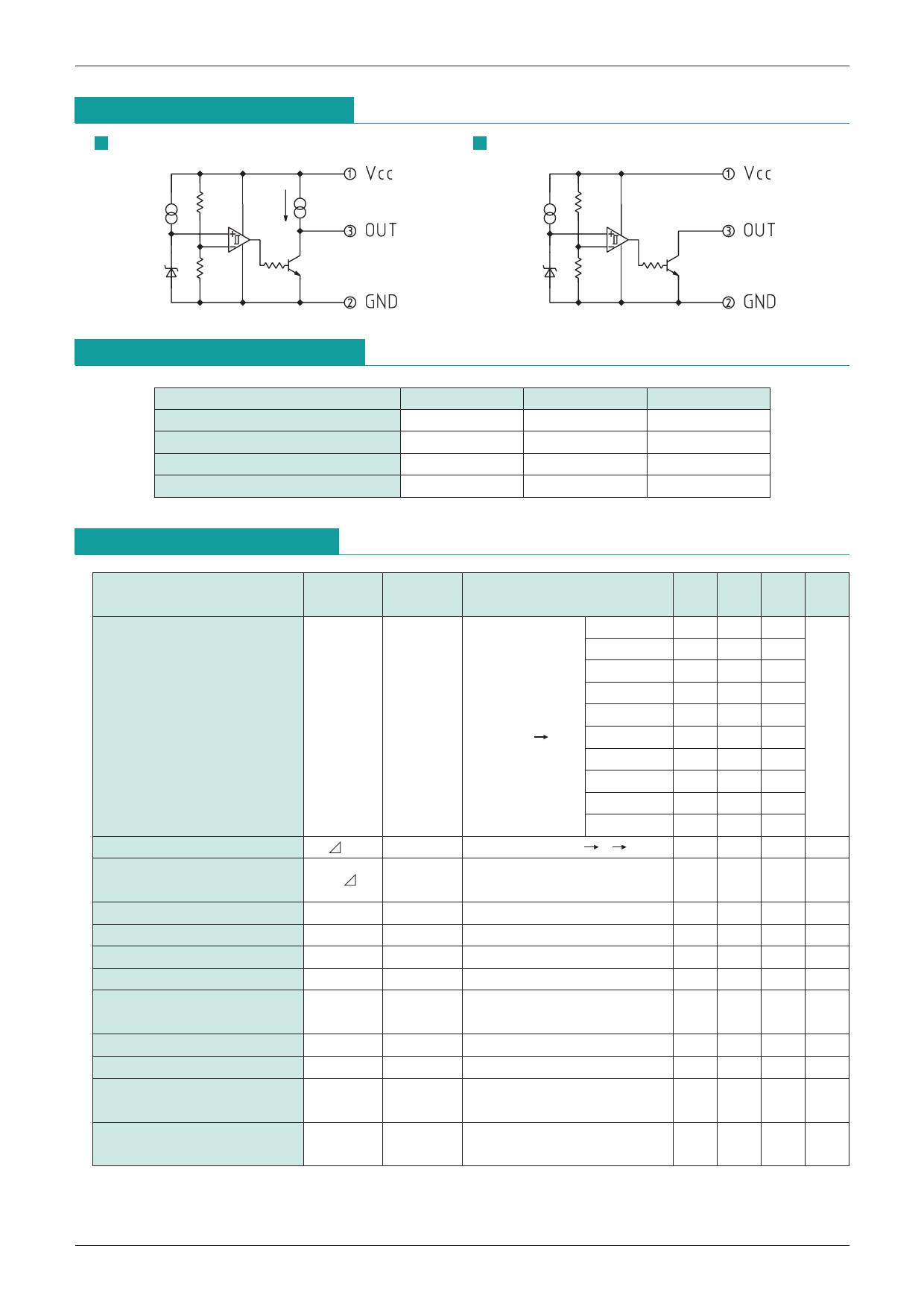
Equivalent Circuit Diagram
PST993
PST994
System Reset PST993, 994
Absolute Maximum Ratings (Ta=25°C)
Item
Storage temperature
Operating temperature
Supply voltage
Allowable loss
Symbol
TSTG
TOPR
VCC
Pd
Ratings
-40~+125
-20~+75
-0.3~10
300
Units
°C
°C
V
mW
Electrical Characteristics (Ta=25°C) (The unit of resistance is Ω unless otherwise indicated.)
Item
Measurement
Symbol
Measurement conditions Min. Typ. Max. Units
Circuit
PST993C 4.27 4.5 4.73
PST993D 4.00 4.2 4.40
PST993E 3.70 3.9 4.10
Detection Voltage
PST993F 3.42 3.6 3.78
V
RL=∞
PST993G 3.13 3.3 3.47
VS
1
VCC=H L
PST993H 2.94 3.1 3.26
PST993I 2.75 2.9 3.05
PST993J 2.56 2.7 2.84
PST993K 2.37 2.5 2.63
PST993L 2.18 2.3 2.42
Hysteresis Voltage
VS
1
RL=∞, VCC=L H L
30 50 100 mV
Detection Voltage
VS/ T
1
Temperature Coefficient
RL=∞, Ta=-20~+75°C
±0.01
%/°C
Low Level Output Voltage
VOL
1
VCC=Vs min. -0.05V, RL=1k
0.1 0.4 V
Output Constant Current
IOC
1
VO=2.5V, VCC=5V, RL=∞
-40 -25 -17 µA
Circuit Current at ON Time
ICCL
1
VCC=Vs min. -0.05V, RL=∞
250 400 µA
Circuit Current at OFF Time ICCH
1
VCC=Vs typ. /0.85V, RL=∞
300 500 µA
"H" Transmission Delay Time tpLH
2
"L" Transmission Delay Time tpHL
2
CL=100pF
CL=100pF
20
µS
*1
1
µS
Operating Threshold Voltage VOPL
1
RL=4.7k, VOL <= 0.4V
0.65 0.85 V
Output Current at ON Time 1 IOL1
1
RL=∞, VO=0.4V
6 15
mA
VCC=VS min. -0.05V
Output Current at ON Time 2 IOL2
1
Ta=-20~+75°C, RL=∞
4
mA
VO=0.4V, VCC=Vs min. -0.05V
*Do not apply onto the OUT terminal any voltage higher than that at the VCC terminal.
*( 1) The tpLH is a function of the charging time of CL by output constant current.
The delay time of this IC is about 1 µS.
Share Link: 