PM9605APE Ver la hoja de datos (PDF) - South African Micro Electronic Systems
Número de pieza
componentes Descripción
Fabricante
PM9605APE
South African Micro Electronic Systems

PM9605APE Datasheet PDF : 14 Pages
| |||
PM9604/5AP
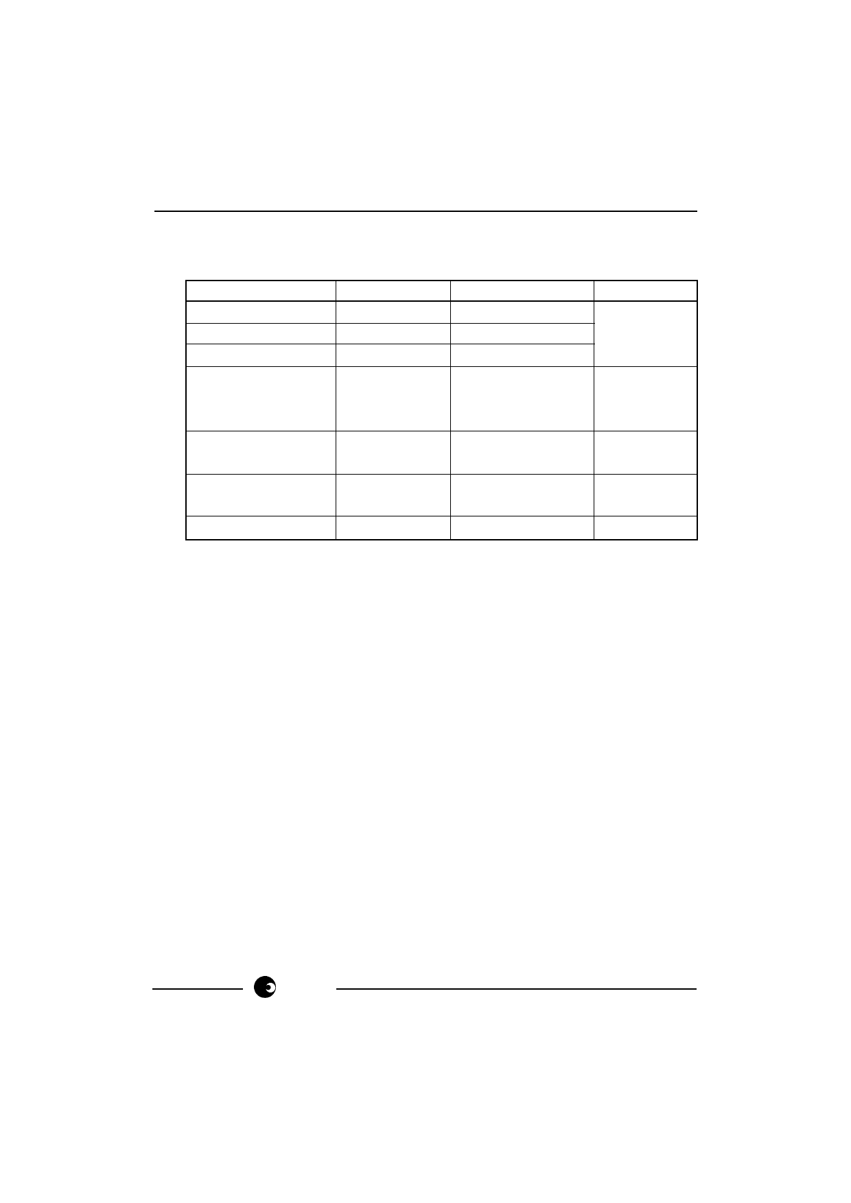
6. Jumper Configurations
The jumper configufations required for the two devices types are shown below:
JUMPER POSITION
JP1 1 - 2
JP2 1 - 2
JP3 1 - 2
JP4 1 - 2
2-3
3-4
JP5 1 - 2
2-3
JP6 1 - 2
2-3
JP7 1 - 2
SA9604A
Insert
Insert
Insert
Remove
Remove
Insert (SCK)
Remove
Insert (CS)
Remove
Insert (DI)
Remove
SA9605A
Insert
Insert
Insert
Insert (FOUT1)
Insert (FOUT2)
Remove
Insert (PGM1=1)
Remove (PGM1=0)
Insert (PGM0=1)
Remove (PGM0=0)
Insert
NOTES
Note 1
Note 2
Note 3
Note 3
Note 1:
Note 2:
Note 3:
The removal of the link on the current sensor input must only be
performed during calibration.
Only one of the two output pulse signals on the SA9605A may be
selected at any one time using this module. In a users application both
of these signals may be used.
The SA9605A I.C. has on-board pull-down resistors, pull-up connection
to VDD is, therefore, the only connection which must be catered for.
sames
5/14
Share Link: