KK130F Ver la hoja de datos (PDF) - SanRex Corporation
Número de pieza
componentes Descripción
Fabricante
KK130F Datasheet PDF : 2 Pages
| |||
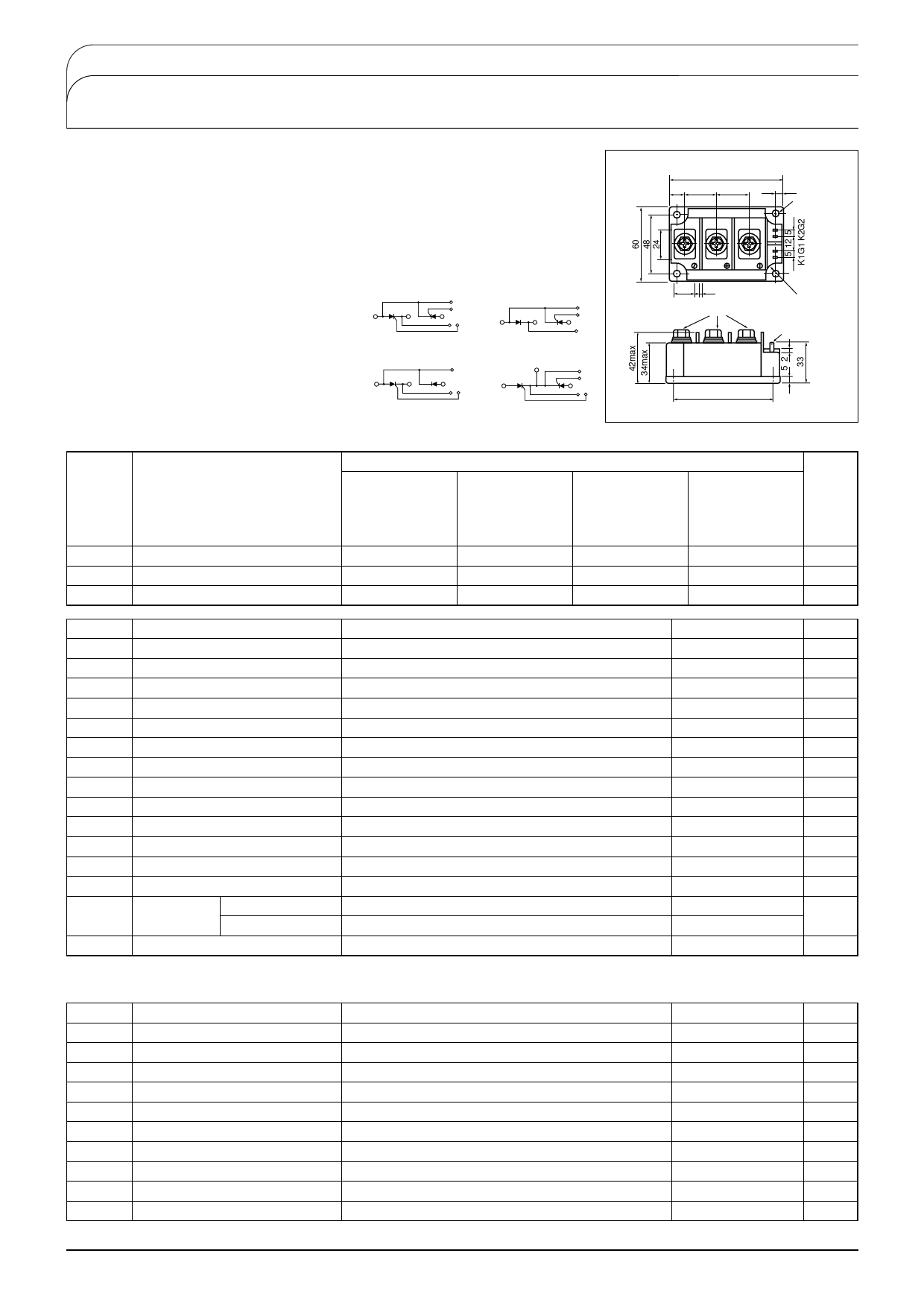
THYRISTOR MODULE
PK(PD,PE,KK)130F
Power Thyristor/Diode Module PK130F series are designed for various rectifier circuits
and power controls. For your circuit application. following internal connections and wide
voltage ratings up to 1,600V are available. Two elements in a package and electrically
isolated mounting base make your mechanical design easy.
UL:E76102(M)
92
12 26
26
7
4-φ6(M5)
● IT(AV) 130A, IT(RMS) 205A, ITSM 4400A
● di/dt 200 A/μs
● dv/dt 500V/μs
(Applications)
Various rectifiers
AC/DC motor drives
Heater controls
Light dimmers
Static switches
■Maximum Ratings
Symbol
Item
VRRM
VRSM
VDRM
*Repetitive Peak Reverse Voltage
*Non-Repetitive Peak Reverse Voltage
Repetitive Peak Off-State Voltage
3
A1K2
2
(K2)
K2
G2
1
(A2)K1 G1
PK
3
A1K2
2
(K2)
K2
1
(A2)K1 G1
PD
3
A1K2
2
(K2)
K2
G2
1
(A2)K1
PE
1
(A1)
2
K2
G2
1
(A2)K1 G1
KK
18 2
M8×14
R8.0
♯110TAB
(2.8.0.5T)
80±0.3
Unit:A
PK130F40
PD130F40
PE130F40
KK130F40
400
480
400
Ratings
PK130F80
PD130F80
PE130F80
KK130F80
PK130F120
PD130F120
PE130F120
KK130F120
800
1200
960
1300
800
1200
PK130F160
PD130F160 Unit
PE130F160
KK130F160
1600
V
1700
V
1600
V
Symbol
Item
IT(AV) *Average On-State Current
IT(RMS) *R.M.S. On-State Current
ITSM *Surge On-State Current
I2t *I2t
PGM Peak Gate Power Dissipation
PG(AV) Average Gate Power Dissipation
IFGM Peak Gate Current
VFGM Peak Gate Voltage (Forward)
VRGM Peak Gate Voltage (Reverse)
di/dt Critical Rate of Rise of On-State Current
VISO *Isolation Breakdown Voltage (R.M.S.)
Tj *Operating Junction Temperature
Tstg *Storage Temperature
Mounting
Torque
Mounting(M5)
Terminal(M8)
Mass
Conditions
Single phase, half wave, 180°conduction, Tc:90℃
Single phase, half wave, 180°conduction, Tc:90℃
1/2cycle, 50Hz/60Hz, peak Value, non-repetitive
Value for one cycle of surge current
IG=100mA,Tj=25℃,VD=1/2VDRM,dIG/dt=0.1A/μs
A.C.1minute
Recommended 1.5-2.5(15-25)
Recommended 8.8-10(90-105)
Ratings
130
205
4000/4400
8×10⁴
10
3
3
10
5
200
2500
−40 to +125
−40 to +125
2.7(28)
11(115)
510
Unit
A
A
A
A2S
W
W
A
V
V
A/μs
V
℃
℃
N・m
(㎏f・B)
g
■Electrical Characteristics
Symbol
Item
IDRM Repetitive Peak Off-State Current, max.
IRRM *Repetitive Peak Reverse Current, max.
VTM *Peak On-State Voltage, max.
IGT/VGT Gate Trigger Current/Voltage, max.
VGD Non-Trigger Gate, Voltage. min.
tgt
Turn On Time, max.
dv/dt Critical Rate of Rise of Off-State Voltage, min.
IH
Holding Current, typ.
IL
Lutching Current, typ.
Rth(j-c)*Thermal Impedance, max.
*mark:Thyristor and Diode part. No mark:Thyristor part
Conditions
at VDRM, single phase, half wave, Tj=125℃
at VDRM, single phase, half wave, Tj=125℃
On-State Current 400A, Tj=25℃ Inst. measurement
Tj=25℃,IT=1A,VD=6V
Tj=125℃,VD=1/2VDRM
IT=130A,IG=100mA,Tj=25℃,VD=1/2VDRM,dIG/dt=0.1A/μs
Tj=125℃, VD=2/3VDRM, Exponential wave.
Tj=25℃
Tj=25℃
Junction to case
Ratings
50
50
1.40
100/3
0.25
10
500
50
100
0.2
Unit
mA
mA
V
mA/V
V
μs
V/μs
mA
mA
℃/W
SanRex 50 Seaview Blvd. Port Washington, NY 11050-4618 PH.(516)625-1313 FAX(516)625-8845 E-mail: semi@sanrex.com
Share Link: 