PCD3310AT Ver la hoja de datos (PDF) - Philips Electronics
Número de pieza
componentes Descripción
Fabricante
PCD3310AT Datasheet PDF : 28 Pages
| |||
Philips Semiconductors
Pulse and DTMF diallers with redial
Product specification
PCD3310; PCD3310A
If the CE input is taken to a LOW level for longer than time
period trd (see Figs 11 and 12 and Chapter 12) an internal
reset pulse will be generated at the end of the trd period.
The system changes to the static standby state. Short CE
pulses of < trd will not affect the operation of the device and
reset pulses are not produced.
entries are debounced on both the leading and trailing
edges for approximately time period te as shown in
Figs 11, 12, 13 and 14. Each entry is tested for validity.
When a key is depressed, keyboard scanning starts and
only returns to the sense mode after release of that key.
7.4 Mode selection (PD/DTMF)
7.4.1 PULSE MODE
If PD/DTMF = VSS the pulse mode is selected. Entries of
non-numeric keys are neglected, they are neither stored in
the redial register nor transmitted.
handbook, halfpage ROWS
54321
COLUMNS
1234
7.4.2 DTMF MODE
If PD/DTMF = VDD the dual tone multi-frequency dialling
mode is selected. Each non-function key activated
corresponds to a combination of two tones, one of four
LOW and one of four HIGH frequencies, corresponding to
the key’s row and column in the keyboard matrix.
See Fig.4 and Table 3. The frequencies are transmitted
with a constant amplitude, regardless of power supply
variations. Harmonic content is filtered out thus meeting
the CEPT recommendations.
The transmission time is calibrated for redial. In manual
operation the duration of bursts and pauses is the actual
key depression time, but not less than the minimum
transmission time (tt) or minimum pause time (tp).
7.4.3 MIXED MODE
When the PD/DTMF pin is open-circuit the mixed mode is
selected. After activation of CE or FL (Flash) the device
starts as a pulse dialler and remains in this state until a
non-numeric dial key (A, B, C, D, ∗, #) or the function key >
is activated. Pressing a non-numeric dial key causes the
corresponding DTMF tones to be output, and any
subsequent dialling to be in DTMF mode. Pressing >
causes no output tones, but any subsequent dialling is in
DTMF mode. The > key should be used if the first DTMF
output required is numeric. The device remains in DTMF
dial mode until FL is activated or after a static standby
condition when CE is re-activated.
A connection between the PD/DTMF pin and VDD also
initiates DTMF dialling. Chip enable, FL or a connection of
PD/DTMF pin to VSS sets the device back to pulse dialling.
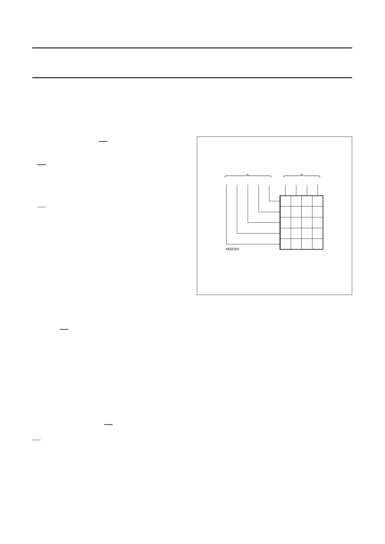
7.5 Keyboard inputs/outputs
The sense column inputs COL 1 to COL 4 and the
scanning row outputs ROW 1 to ROW 5 of the device are
connected to the keyboard as shown in Fig.4. All keyboard
MGE491
123A
456B
7 8 9C
∗ 0 #D
P FL R >
KEYBOARD
Fig.4 Keyboard organization.
ROW 5 of the keyboard contains the following function
keys:
• P = memory clear and programming (notepad)
• FL = flash or register recall
• R = redial
• > = change of dial mode from pulse to DTMF in mixed
dialling mode.
In the pulse dialling mode the valid keys are the
10 numeric dial keys (0 to 9). The non-numeric dial keys
(A, B, C, D, ∗, #) have no effect on the dialling or the redial
storage. Valid function keys are P, R and FL.
In the DTMF mode all dial keys are valid. They are
transmitted as a dual tone combination and at the same
time stored in the redial register. Valid function keys are P,
FL and R.
In the mixed mode all key entries are valid and executed
accordingly.
1996 Nov 21
8
Share Link: 