PCD3310 Ver la hoja de datos (PDF) - Philips Electronics
Número de pieza
componentes Descripción
Fabricante
PCD3310 Datasheet PDF : 28 Pages
| |||
Philips Semiconductors
Pulse and DTMF diallers with redial
Product specification
PCD3310; PCD3310A
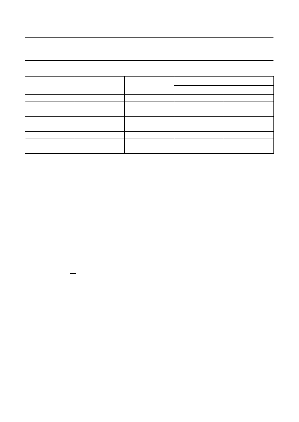
Table 3 Frequency tolerance of the output tones for DTMF signalling; fxtal = 3.579545 MHz
ROW/COLUMN
STANDARD
FREQUENCY (Hz)
TONE OUTPUT
FREQUENCY (Hz)
FREQUENCY DEVIATION
%
Hz
ROW 1
ROW 2
ROW 3
ROW 4
COL 1
COL 2
COL 3
COL 4
697
770
852
941
1 209
1 336
1 477
1 633
697.90
770.46
850.45
943.23
1 206.45
1 341.66
1 482.21
1 638.24
+0.13
+0.06
−0.18
+0.24
−0.21
+0.42
+0.35
+0.32
+0.90
+0.46
−1.55
+2.23
−2.55
+5.66
+5.21
+5.25
7.8 Dial pulse and Flash output (DP/FLO)
This is a combined output which provides control signals
for timing in pulse dialling or for a calibrated line break
(flash or register recall) in both dialling modes.
7.9 Mute output (M1)
The MUTE output can be used to disable the microphone
during dialling.
During pulse dialling the mute output becomes active
HIGH for the period of the inter-digit pause, break time and
make time. It remains at this level until the last digit is
pulsed out.
During DTMF dialling the mute output becomes active
HIGH for the period of tone transmission and remains at
this level until the end of hold-over time. It is also active
HIGH during flash and flash hold-over time.
7.10 Mute output (M1)
Inverted output of M1. In the PCD3310P it is only available
as a bonding option of M1.
7.11 Muting output (M2)
Active HIGH output during actual dialling; i.e. during break
or make time in pulse dialling, or during tone ON/OFF in
DTMF dialling. It is an open drain p-channel output.
8 DIALLING PROCEDURES (see Figs 7, 8 and 9)
8.1 Dialling
After CE has risen to VDD the oscillator starts running and
the Read Address Counter (RAC) is set to the first address
of both the main and temporary redial registers, ready to
redial any stored number (see Fig.6). By dialling the first
valid digit, the Temporary Write Address Counter (TWAC)
will be set to the first address of the temporary register,
and the decoded digit will be stored in the temporary
register at that address. The TWAC is then incremented to
the next address. The first 5 valid digits will be decoded
and stored in the temporary register in this way, and have
no effect on the main register and its associated Write
Address Counter (WAC). After the sixth valid digit is
entered, the TWAC indicates an overflow condition.
The data from the temporary register will be copied into the
5 least significant places of the main register and the
TWAC into the WAC. The sixth digit, and all subsequent
digits will be stored in the main register (a total of not more
than 23). If more than 23 digits are entered redial will be
inhibited. If not more than 5 digits are entered only the
temporary register and the associated TWAC are affected.
All entries are debounced on both the leading and trailing
edges for at least time period te as shown in Figs 11, 12,
13 and 14.
Each entry is tested for validity before being stored in the
redial registers.
• For DTMF dialling all dial keys are valid
• For pulse dialling only numeric dial keys are valid.
Simultaneous to their acceptance and corresponding to
the selected mode (pulse, DTMF or mixed), the entries are
transmitted as pulse-trains or as DTMF frequencies in
accordance with PTT requirements. Non-numeric dial key
entries are neglected during pulse dialling; they are neither
stored nor transmitted.
1996 Nov 21
10
Share Link: 