PCA9509 Ver la hoja de datos (PDF) - NXP Semiconductors.
Número de pieza
componentes Descripción
Fabricante
PCA9509 Datasheet PDF : 24 Pages
| |||
NXP Semiconductors
PCA9509
Level translating I2C-bus/SMBus repeater
6.2 I2C-bus systems
As with the standard I2C-bus system, pull-up resistors are required to provide the logic
HIGH levels on the buffered bus (standard open-collector configuration of the I2C-bus).
The size of these pull-up resistors depends on the system. Each of the port A I/Os has an
internal pull-up current source and does not require the external pull-up resistor. Port B is
designed to work with Standard-mode and Fast-mode I2C-bus devices in addition to
SMBus devices. Standard-mode I2C-bus devices only specify 3 mA output drive; this
limits the termination current to 3 mA in a generic I2C-bus system where Standard-mode
devices and multiple masters are possible. Under certain conditions higher termination
currents can be used.
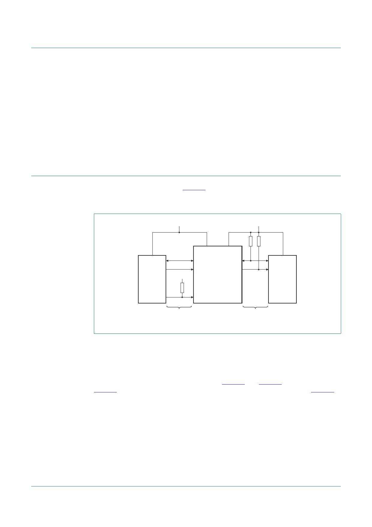
7. Application design-in information
A typical application is shown in Figure 5. In this example, the CPU is running on a 1.35 V
I2C-bus while the master is connected to a 3.3 V bus. Both buses run at 400 kHz. Master
devices can be placed on either bus.
1.35 V
3.3 V
SDA
SCL
MASTER
CPU
1.35 V
10 kΩ
VCC(A)
10 kΩ
VCC(B)
A1
B1
A2
B2
PCA9509
EN
10 kΩ
SDA
SCL
SLAVE
400 kHz
bus A
bus B
002aac128
Fig 5. Typical application
When port B of the PCA9509 is pulled LOW by a driver on the I2C-bus, a CMOS
hysteresis detects the falling edge when it goes below 0.3VCC(B) and causes the internal
driver on port A to turn on, causing port A to pull down to about 0.2 V. When port A of the
PCA9509 falls, first a comparator detects the falling edge and causes the internal driver
on port B to turn on and pull the port B pin down to ground. In order to illustrate what
would be seen in a typical application, refer to Figure 6 and Figure 7. If the bus master in
Figure 5 were to write to the slave through the PCA9509, waveforms shown in Figure 6
would be observed on the B bus. This looks like a normal I2C-bus transmission.
On the A bus side of the PCA9509, the clock and data lines are driven by the master and
swing nearly to ground. After the eighth clock pulse, the slave replies with an ACK that
causes a LOW on the A side equal to the VOL of the PCA9509, which the master
recognizes as a LOW. It is important to note that any arbitration or clock stretching events
require that the LOW level on the A bus side at the input of the PCA9509 (VIL) is below
VILc to be recognized by the PCA9509 and then transmitted to the B bus side.
PCA9509
Product data sheet
All information provided in this document is subject to legal disclaimers.
Rev. 7 — 4 November 2014
© NXP Semiconductors N.V. 2014. All rights reserved.
6 of 24
Share Link: 