MT8870 Ver la hoja de datos (PDF) - Mitel Networks
Número de pieza
componentes Descripción
Fabricante
MT8870 Datasheet PDF : 12 Pages
| |||
MT8870D/MT8870D-1 ISO2-CMOS
condition is maintained (ESt remains high) for the
validation period (tGTP), vc reaches the threshold
(VTSt) of the steering logic to register the tone pair,
latching its corresponding 4-bit code (see Table 1)
into the output latch. At this point the GT output is
activated and drives vc to VDD. GT continues to drive
high as long as ESt remains high. Finally, after a
short delay to allow the output latch to settle, the
delayed steering output flag (StD) goes high,
signalling that a received tone pair has been
registered. The contents of the output latch are made
available on the 4-bit output bus by raising the three
state control input (TOE) to a logic high. The
steering circuit works in reverse to validate the
interdigit pause between signals. Thus, as well as
rejecting signals too short to be considered valid, the
receiver will tolerate signal interruptions (dropout)
too short to be considered a valid pause. This facility,
together with the capability of selecting the steering
time constants externally, allows the designer to
tailor performance to meet a wide variety of system
requirements.
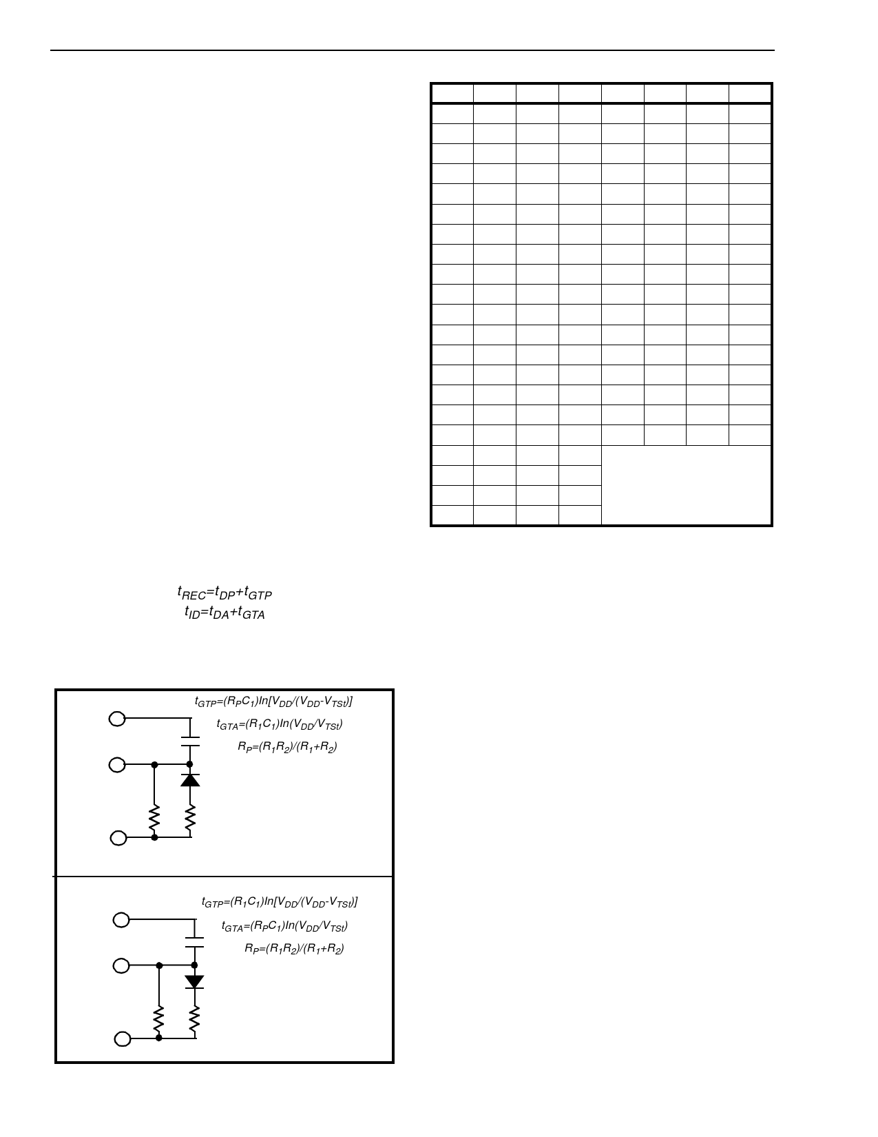
Guard Time Adjustment
In many situations not requiring selection of tone
duration and interdigital pause, the simple steering
circuit shown in Figure 4 is applicable. Component
values are chosen according to the formula:
tREC=tDP+tGTP
tID=tDA+tGTA
The value of tDP is a device parameter (see Figure
11) and tREC is the minimum signal duration to be
recognized by the receiver. A value for C of 0.1 µF is
VDD
St/GT
tGTP=(RPC1)In[VDD/(VDD-VTSt)]
tGTA=(R1C1)In(VDD/VTSt)
C1
RP=(R1R2)/(R1+R2)
R1
R2
ESt
a) decreasing tGTP; (tGTP<tGTA)
VDD
St/GT
tGTP=(R1C1)In[VDD/(VDD-VTSt)]
tGTA=(RPC1)In(VDD/VTSt)
C1
RP=(R1R2)/(R1+R2)
R1
R2
ESt
b) decreasing tGTA; (tGTP>tGTA)
Figure 5 - Guard Time Adjustment
4-14
Digit TOE INH ESt Q4
Q3
Q2
Q1
ANY L
X
H
Z
Z
Z
Z
1
H
X
H
0
0
0
1
2
H
X
H
0
0
1
0
3
H
X
H
0
0
1
1
4
H
X
H
0
1
0
0
5
H
X
H
0
1
0
1
6
H
X
H
0
1
1
0
7
H
X
H
0
1
1
1
8
H
X
H
1
0
0
0
9
H
X
H
1
0
0
1
0
H
X
H
1
0
1
0
*
H
X
H
1
0
1
1
#
H
X
H
1
1
0
0
A
H
L
H
1
1
0
1
B
H
L
H
1
1
1
0
C
H
L
H
1
1
1
1
D
H
L
H
0
0
0
0
A
H
H
L
B
H
H
L undetected, the output code
will remain the same as the
C
H
H
L previous detected code
D
H
H
L
Table 1. Functional Decode Table
L=LOGIC LOW, H=LOGIC HIGH, Z=HIGH IMPEDANCE
X = DON‘T CARE
recommended for most applications, leaving R to be
selected by the designer.
Different steering arrangements may be used to
select independently the guard times for tone
present (tGTP) and tone absent (tGTA). This may be
necessary to meet system specifications which place
both accept and reject limits on both tone duration
and interdigital pause. Guard time adjustment also
allows the designer to tailor system parameters
such as talk off and noise immunity. Increasing tREC
improves talk-off performance since it reduces the
probability that tones simulated by speech will
maintain signal condition long enough to be
registered. Alternatively, a relatively short tREC with
a long tDO would be appropriate for extremely noisy
environments where fast acquisition time and
immunity to tone drop-outs are required. Design
information for guard time adjustment is shown in
Figure 5.
Share Link: 