L4977A Ver la hoja de datos (PDF) - STMicroelectronics
Número de pieza
componentes Descripción
Fabricante
L4977A Datasheet PDF : 21 Pages
| |||
L4977A
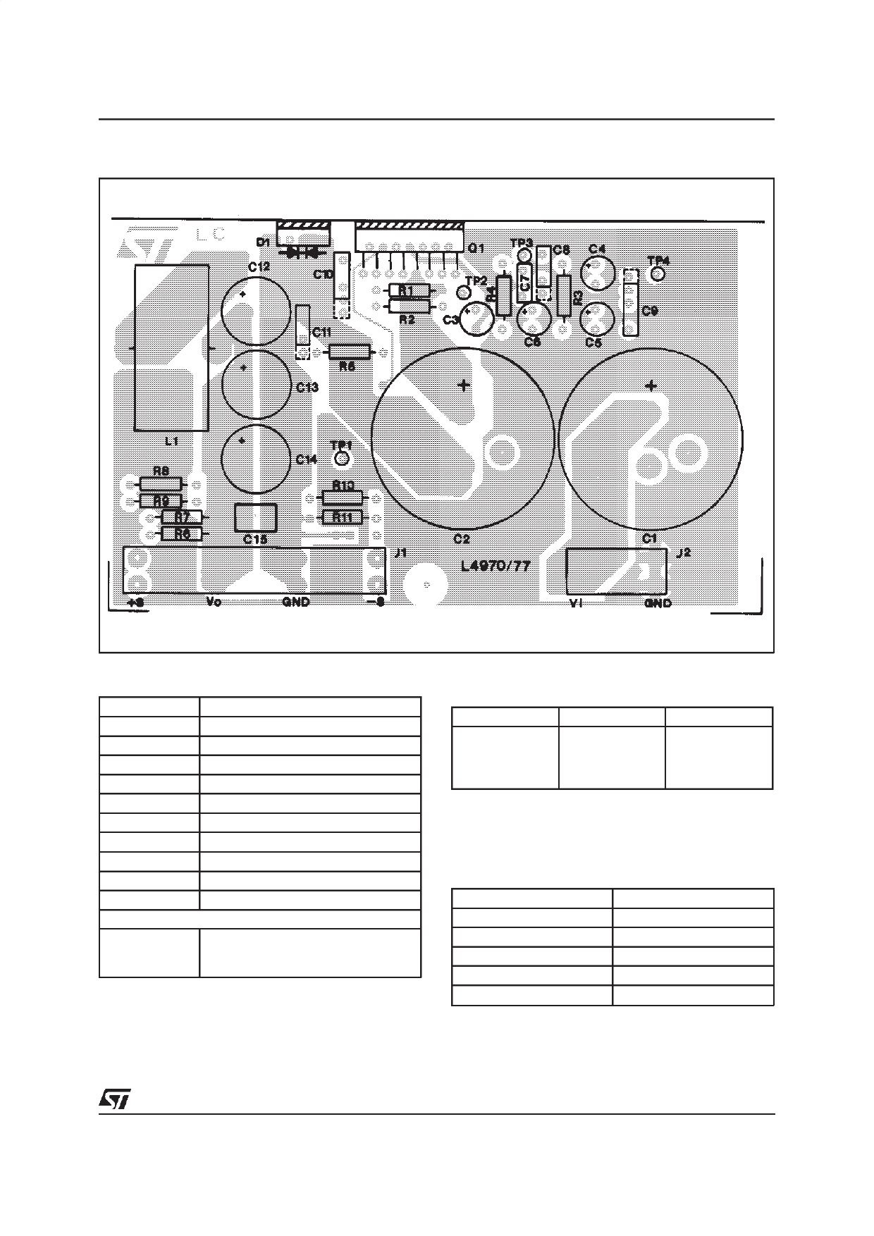
Figure 6a: P.C. Board (components side) and Components Layout of Figure 5 (1:1 scale).
PARTS LIST
R1 = 30KΩ
R2 = 10KΩ
R3 = 15KΩ
C1, C2 = 3300µF 63VL EYF (ROE
C3, C4, C5, C6 = 2.2µF
C7 = 390pF Film
R4 = 16KΩ
R5 = 22Ω 0,5W
R6 = 4K7
C8 = 22nF MKT 1817 (ERO)
C9 = 2.2nF KP1830
R7 = 10Ω
C10 = 220nF MKT
R8 = see tab. A C11 = 2.2nF MP1830
R9 = OPTION **C12, C13, C14 = 220µF 40VL EKR
R10 = 4K7
C15 = 1µF Film
R11 = 10Ω
D1 = MBR 1560CT (or 16A/60V or equivalent)
L1 = 40µH
core 58071 MAGNETICS
27 TURNS Ø 1,3mm (AWG 16)
COGEMA 949178
* 2 capacitors in parallel to increase input RMS current capability
** 3 capacitors in parallel to reduce total output ESR
Table A
V0
12V
15V
18V
24V
R9
4.7kΩ
4.7kΩ
4.7kΩ
4.7kΩ
R7
6.2kW
9.1kΩ
12kΩ
18kΩ
Table B
SUGGESTED BOOTSTRAP CAPACITORS
Operating Frequency
f = 20KHz
f = 50KHz
f = 100KHz
f = 200KHz
f = 500KHz
Bootstrap Cap.c10
≥680nF
≥470nF
≥330nF
≥220nF
≥100nF
9/21
Share Link: 