OP90 Ver la hoja de datos (PDF) - Analog Devices
Número de pieza
componentes Descripción
Fabricante
OP90 Datasheet PDF : 13 Pages
| |||
OP90
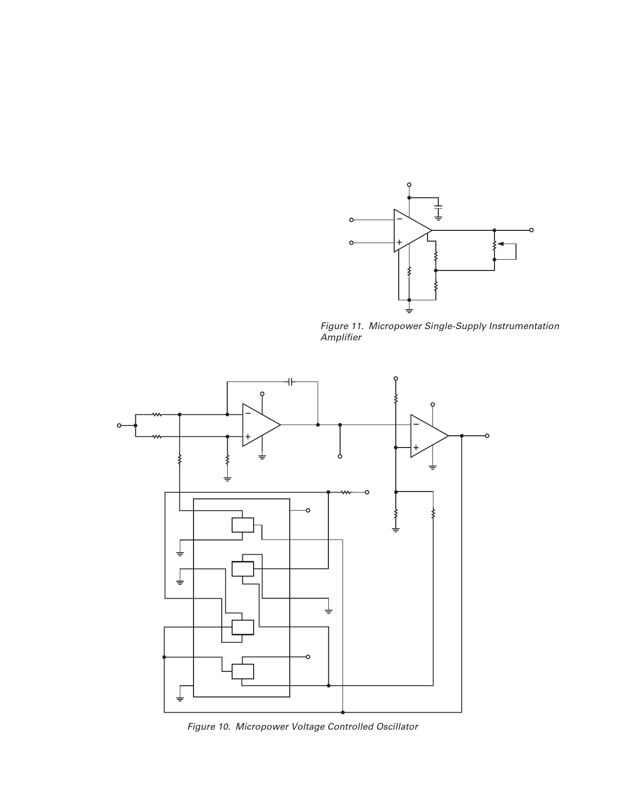
Micropower Voltage-Controlled Oscillator
Two OP90s in combination with an inexpensive quad CMOS
switch comprise the precision VCO of Figure 10. This circuit
provides triangle and square wave outputs and draws only 50 µA
from a single 5 V supply. A1 acts as an integrator; S1 switches
the charging current symmetrically to yield positive and negative
ramps. The integrator is bounded by A2 which acts as a Schmitt
trigger with a precise hysteresis of 1.67 V, set by resistors R5,
R6, and R7, and associated CMOS switches. The resulting output
of A1 is a triangular wave with upper and lower levels of 3.33 V
and 1.67 V. The output of A2 is a square wave with almost
rail-to-rail swing. With the components shown, frequency of
operation is given by the equation:
( ) fOUT = VCONTROL V × 10 Hz /V
but this is easily changed by varying C1. The circuit operates
well up to a few hundred hertz.
Micropower Single-Supply Instrumentation Amplifier
The simple instrumentation amplifier of Figure 11 provides over
110 dB of common-mode rejection and draws only 15 µA of
supply current. Feedback is to the trim pins rather than to the
inverting input. This enables a single amplifier to provide differ-
ential to single-ended conversion with excellent common-mode
rejection. Distortion of the instrumentation amplifier is that of a
differential pair, so the circuit is restricted to high gain applica-
tions. Nonlinearity is less than 0.1% for gains of 500 to 1000
over a 2.5 V output range. Resistors R3 and R4 set the voltage
gain and, with the values shown, yield a gain of 1000. Gain
tempco of the instrumentation amplifier is only 50 ppm/°C.
Offset voltage is under 150 µV with drift below 2 µV/°C. The
OP90’s input and output voltage ranges include the negative
rail which allows the instrumentation amplifier to provide true
“zero-in, zero-out” operation.
+5V
0.1F
–IN
2
7
6
OP90
+IN
3
1
4
5
R4
3.9M⍀
R2
500k⍀
GAIN
ADJUST
R1
4.3M⍀
R3
1M⍀
VOUT
Figure 11. Micropower Single-Supply Instrumentation
Amplifier
C1
+5V
VCONTROL
R1
200k⍀
R2
200k⍀
R3
100k⍀
+5V
75nF
2
7
OP90
6
3 A1
4
R4
200k⍀
TRIANGLE
OUT
R5
200k⍀
+5V
2
7
OP90
6
3 A2
4
SQUARE
OUT
1 IN/OUT CD4066
S1
2 OUT/IN
R8
+5V
200k⍀
VDD 14
+5V
CONT 13
R6
200k⍀
R7
200k⍀
3 OUT/IN
S2
CONT 12
4 IN/OUT
IN/OUT 11
5 CONT
6 CONT
7 VSS
OUT/IN 10
S3
OUT/IN 9
+5V
S4
IN/OUT 8
Figure 10. Micropower Voltage Controlled Oscillator
–10–
REV. C
Share Link: 