OMR9601SC Ver la hoja de datos (PDF) - International Rectifier
Número de pieza
componentes Descripción
Fabricante
OMR9601SC Datasheet PDF : 8 Pages
| |||
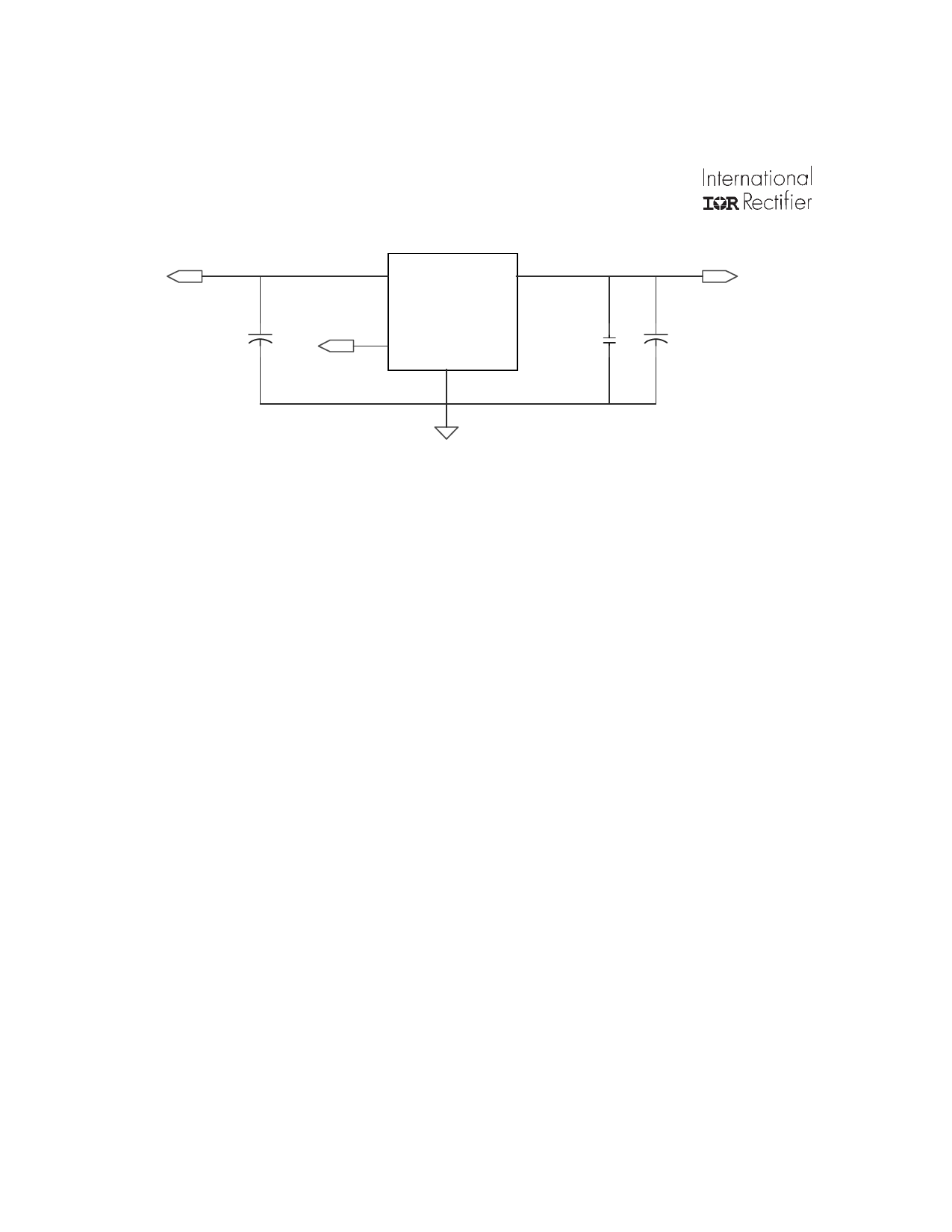
OMR9601SC
Vin
100uF 16V
Tantalum
Vin
Vout
OMR9601
.
SHDN
1.0uF x 10
Ceramic X7R
GND
Vout
1000uF 6.3V
Low ESR Tantalum
Ground
Fig 6. Typical Application Circuit
Input Capacitance
Recommended input capacitance for a generic application is a 100µF, 16V tantalum capacitor. However,
the input capacitance is not critical to the stability of the regulator and is therefore application dependent. In
designs with a clean bus voltage that is situated close to the input of the regulator, only a small ceramic
capacitor will be needed to decouple high frequency noise. On the other hand, in designs with a noisy bus,
a larger capacitor will be needed. Care should be taken to ensure that the input to the regulator is
sufficiently free of noise and disturbances.
Output Capacitance
Like most ultra low dropout voltage regulators, OMR9601 requires the use of an output capacitor as part
of the device frequency compensation. The device requires a minimum of 220µF tantalum to ensure stability.
Many different types of capacitor are available and have widely varying characteristics. These capacitors
differ in capacitor tolerance, equivalent series resistance (ESR), equivalent series inductance and
capacitance temperature coefficient. The OMR9601 frequency compensation optimizes frequency
response with low ESR capacitors. In general, use capacitors with an ESR of less than 50 mΩ for heavy
load applications.
High quality bypass capacitors must also be used to limit the high frequency noise generated by the load.
Multiple small ceramic capacitors are typically required to limit parasitic inductance (ESL) and ESR in the
capacitors to acceptable levels.
The upper limit of the capacitance is governed by the delayed over-current latch function of the regulator.
The regulator has a protection circuit that will latch the device off in the event of a short circuit. However,
since it is known that the regulator will draw a large in-rush current upon startup, the latch-off is delayed
by about 10ms to allow the output capacitors to charge to a steady state without shutting down. During
this period, the regulator will have an output current at its maximum of around 5A typical. Therefore, the
maximum output capacitance can be as high as 20,000uF without causing device to latch-off during start-up.
Figure 6 shows a typical application circuit. The output load capacitor consists of one tantalum capacitor
(or more in parallel) of 1,000µF with ESR no high than 50 mΩ, and 10 x 1.0µF X7R ceramic caps. This
will give approximately 59 degrees phase and 24dB gain margin.
6
www.irf.com
Share Link: 