NTE1510 Ver la hoja de datos (PDF) - NTE Electronics
Número de pieza
componentes Descripción
Fabricante
NTE1510 Datasheet PDF : 2 Pages
| |||
Recommended Operating Conditions:
Supply Voltage Range . . . . . . . . . . . . . . . . . . . . . . . . . . . . . . . . . . . . . . . . . . . . . . . . . . . . . . . . . 4V to 18V
Rated Supply Voltage . . . . . . . . . . . . . . . . . . . . . . . . . . . . . . . . . . . . . . . . . . . . . . . . . . . . . . . . . . . . . . . 10V
Electrical Characteristics: (TA= +25°C, VCC = 10V unless otherwise specified)
Parameter
Symbol
Test Conditions
Min Typ Max Unit
Supply Voltage Range
Fullscale Input Voltage
Step Voltage
Input Current
Circuit Current
Output 1 LED Drive Voltage (Pin6)
Output 2 LED Drive Voltage (Pin7)
Output 3 LED Drive Voltage (Pin8)
Output 4 LED Drive Voltage (Pin1)
Output 5 LED Drive Voltage (Pin2)
VCC
VINF
Vstep
IIN
ICC
VIT(6)
VIT(7)
VIT(8)
VIT(1)
VIT(2)
VIN = 0V, Note 2
VIN = 0V
RL = 1.5kΩ, IL = 100µA,
Using red GaAIAs LEDs
4 10 18 V
– 1320 – mV
– 210 – mV
– 0.1 1.0 µA
– 5 8 mA
170 230 300 mV
380 450 530 mV
580 660 730 mV
780 860 940 mV
980 1070 1180 mV
Note 2. Current flowing from Pin4 is taken as positive current.
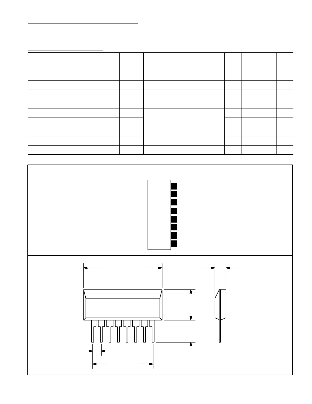
Pin Connection Diagram
(Front View)
8 LED3
7 LED2
6 LED1
5 VCC
4 Input
3 GND
2 LED5
1 LED4
.768 (19.52) Max
.118 (3.0) Max
1
8
.100 (2.54) Typ
.700 (17.78)
.264 (6.72)
Max
.165 (4.2)
Min
Share Link: 