NJU7384 Ver la hoja de datos (PDF) - Japan Radio Corporation
Número de pieza
componentes Descripción
Fabricante
NJU7384 Datasheet PDF : 10 Pages
| |||
NJU7384
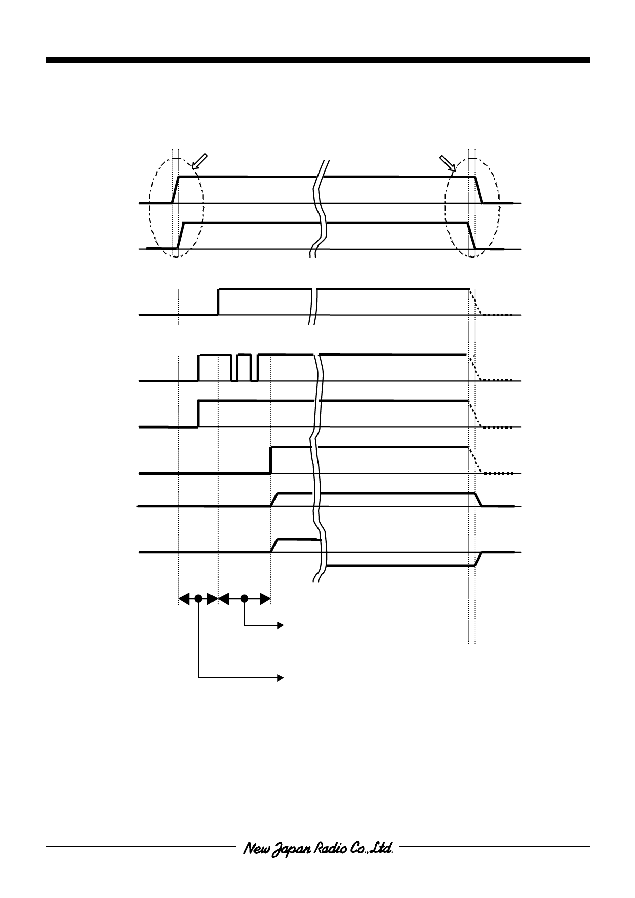
s POWER SUPPLY ON/OFF TIMING
Regarding the switch-on sequence of the logic power supply VDD and the motor power supply VMM, input VDD after
VMM has risen. The recommended sequence is shown below.
ON
VDD ≤VMM
OFF
VDD ≤VMM
VMM
VDD
The RESET signal is "L" level in the range of turning ON . And Phase logic is initialized.
RESET
The STEP terminal is a negative edge active.
If STEP input terminal is no Signal. It signal level is fixed at “H “ level .
STEP
HSM/DIR
ENABLE
IA
IB
Excitation phase backup section
Phase logic initialization section
s RECOMMENDED STEP MODE CHANGEOVER (HSM)
The current flowing through the stepping motor must be controlled continuously so that a mis-step does not occur.
Also, the following precautions must be observed concerning changing of the setting of the HSM input.
(1) A mis-step does not occur during changeover from a full step to a half step
(2) Regarding changeover from a half step to a full step,
(a) A mis-step does not occur during changeover from a half step (excitation sequence 0, 2, 4, 6) to a full step.
(b) A mis-step occurs during changeover from a half step (excitation sequence 1, 3, 5, 7) to a full step.
For the above reason, it is recommended that mode changeover from a half step to a full step be carried out during
the period when the RESET input is “L” logic.
-6-
Ver.2007-08-20
Share Link: 