NCP699 Ver la hoja de datos (PDF) - ON Semiconductor
Número de pieza
componentes Descripción
Fabricante
NCP699 Datasheet PDF : 8 Pages
| |||
NCP699
APPLICATIONS INFORMATION
A typical application circuit for the NCP699 series is
shown in Figure 1, front page.
Input Decoupling (Cin)
A 1.0 mF capacitor either ceramic or tantalum is
recommended and should be connected close to the NCP699
package. Higher values and lower ESR will improve the
overall line transient response.
TDK capacitor: C2012X5R1C105K, or C1608X5R1A105K
Output Decoupling (Cout)
The NCP699 is a stable regulator and does not require any
specific Equivalent Series Resistance (ESR) or a minimum
output current. Capacitors exhibiting ESRs ranging from a
few mW up to 5.0 W can thus safely be used. The minimum
decoupling value is 1.0 mF and can be augmented to fulfill
stringent load transient requirements. The regulator accepts
ceramic chip capacitors as well as tantalum capacitors.
Larger values improve noise rejection and load regulation
transient response.
TDK capacitor: C2012X5R1C105K, C1608X5R1A105K,
or C3216X7R1C105K
Enable Operation
The enable pin will turn on the regulator when pulled high
and turn off the regulator when pulled low. These limits of
threshold are covered in the electrical specification section
of this data sheet. If the enable is not used then the pin should
be connected to Vin.
Hints
Please be sure the Vin and Gnd lines are sufficiently wide.
When the impedance of these lines is high, there is a chance
to pick up noise or cause the regulator to malfunction.
Set external components, especially the output capacitor,
as close as possible to the circuit, and make leads as short as
possible.
Thermal
As power across the NCP699 increases, it might become
necessary to provide some thermal relief. The maximum
power dissipation supported by the device is dependent
upon board design and layout. Mounting pad configuration
on the PCB, the board material and also the ambient
temperature effect the rate of temperature rise for the part.
This is stating that when the NCP699 has good thermal
conductivity through the PCB, the junction temperature will
be relatively low with high power dissipation applications.
The maximum dissipation the package can handle is
given by:
PD
+
TJ(max) *TA
RqJA
If junction temperature is not allowed above the
maximum 125°C, then the NCP699 can dissipate up to
400 mW @ 25°C.
The power dissipated by the NCP699 can be calculated
from the following equation:
Ptot + ƪVin * Ignd (@Iout)ƫ ) [Vin * Vout] * Iout
or
VinMAX
+
Ptot ) Vout * Iout
Ignd(@Iout) ) Iout
If an 150 mA output current is needed then the ground
current from the data sheet is 40 mA. For an NCP699 (3.0 V),
the maximum input voltage will then be 5.65 V.
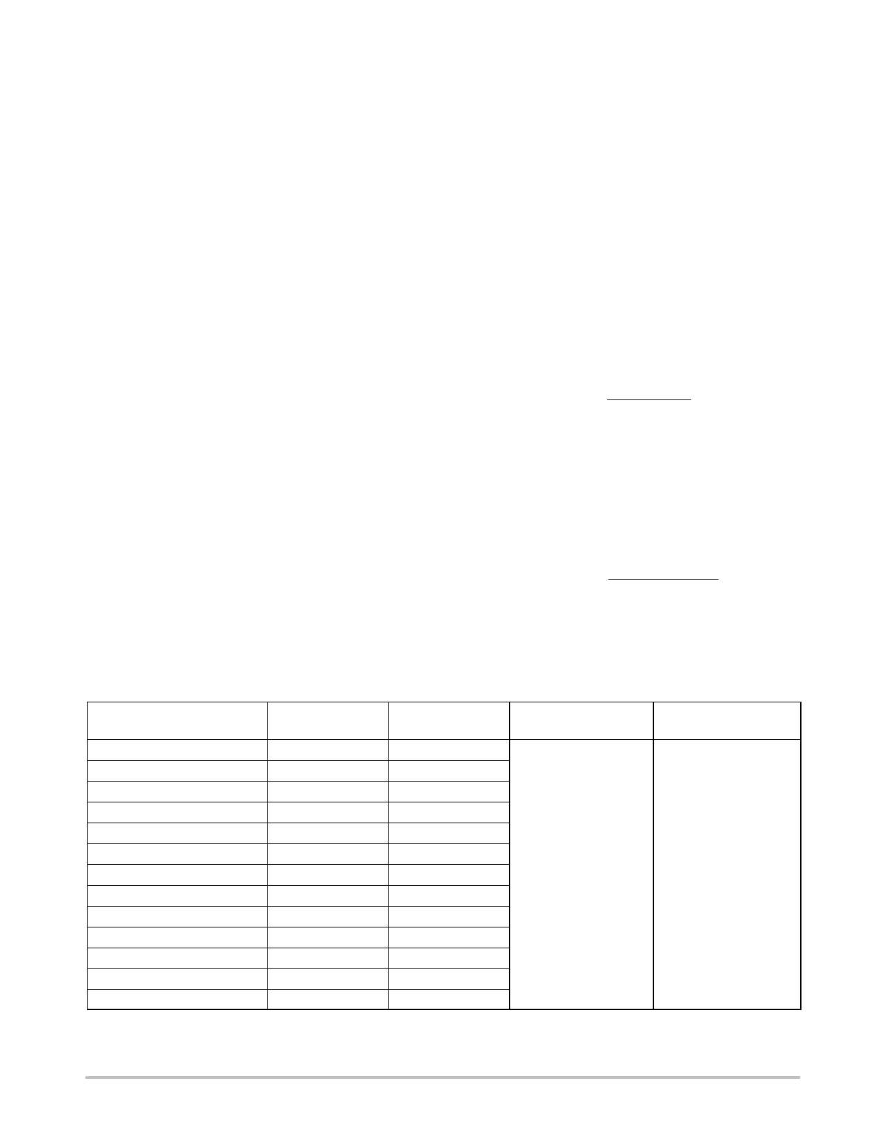
ORDERING INFORMATION
Device
Nominal
Output Voltage*
Marking
Package
Shipping†
NCP699SN13T1G
1.3
LJY
NCP699SN14T1G
1.4
AA4
NCP699SN15T1G
1.5
LJP
NCP699SN18T1G
1.8
LJS
NCP699SN25T1G
2.5
LJT
NCP699SN28T1G
NCP699SN29T1G
NCP699SN30T1G
2.8
LJU
2.9
ACP
TSOP−5
(Pb−Free)
3000 Units/
7″ Tape & Reel
3.0
LJV
NCP699SN31T1G
3.1
AAE
NCP699SN33T1G
3.3
LJW
NCP699SN34T1G
3.4
ACF
NCP699SN45T1G
4.5
ACQ
NCP699SN50T1G
5.0
LJX
*Additional voltages in 100 mV steps are available upon request by contacting your ON Semiconductor representative.
†For information on tape and reel specifications, including part orientation and tape sizes, please refer to our Tape and Reel Packaging
Specification Brochure, BRD8011/D.
http://onsemi.com
7
Share Link: 