NCP1077(2014) Ver la hoja de datos (PDF) - ON Semiconductor
Número de pieza
componentes Descripción
Fabricante
NCP1077 Datasheet PDF : 28 Pages
| |||
NCP1070, NCP1071, NCP1072, NCP1075, NCP1076, NCP1077
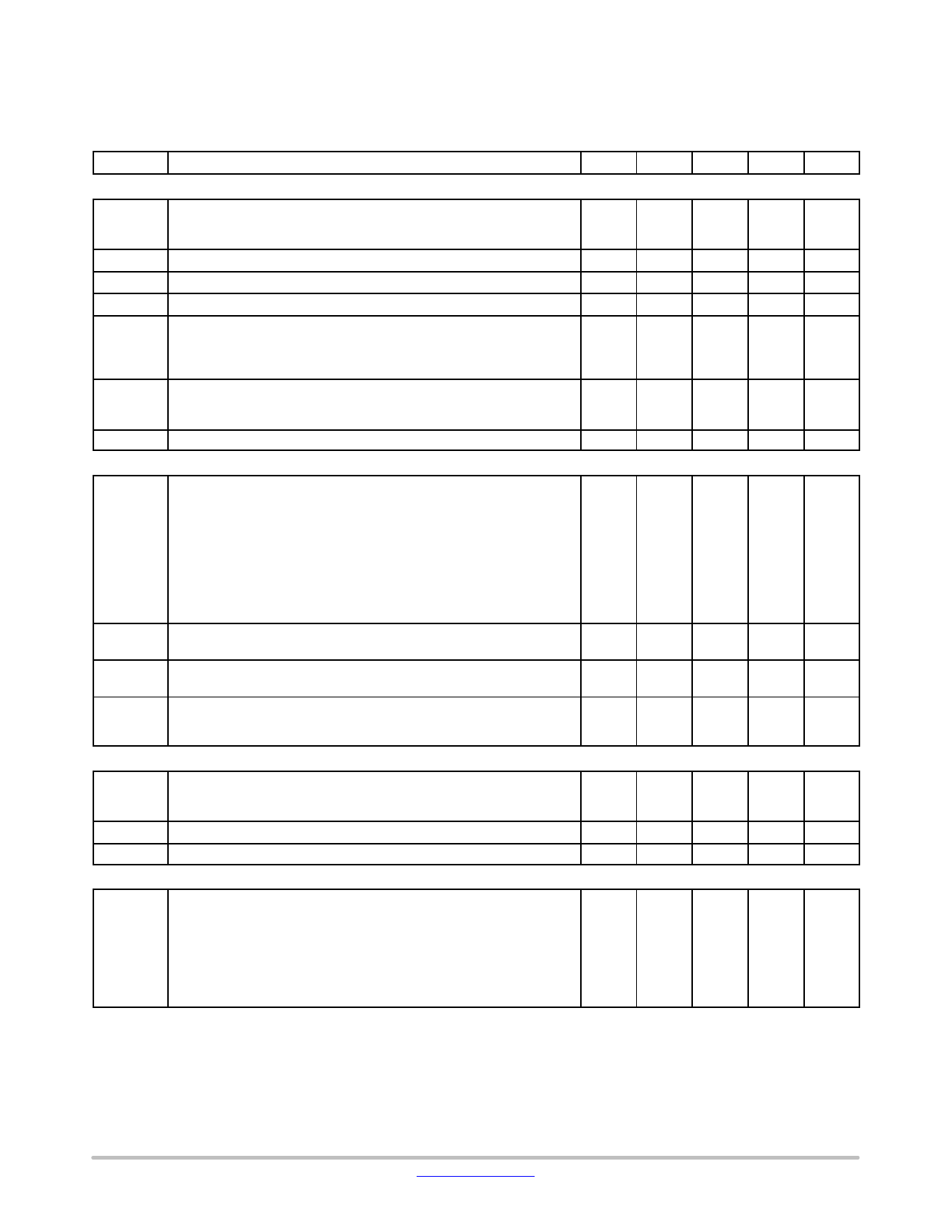
ELECTRICAL CHARACTERISTICS
(For typical values TJ = 25°C, for min/max values TJ = −40°C to +125°C, VCC = 8 V unless otherwise noted)
Symbol
Rating
Pin
Min
Typ
Max
Unit
POWER SWITCH CIRCUIT
RDS(on)
Power Switch Circuit on−state resistance (Id = 50 mA)
NCP1070/71
TJ = 25°C
TJ = 125°C
NCP1072/75
TJ = 25°C
TJ = 125°C
NCP1076/77
TJ = 25°C
TJ = 125°C
BVDSS
Power Switch Circuit & Startup breakdown voltage
(ID(off) = 120 mA, TJ = 25°C)
IDSS(off) Power Switch & Startup breakdown voltage off−state leakage current
TJ = 125°C (Vds = 700 V)
Switching characteristics (RL=50 W, VDS set for Idrain = 0.7 x Ilim)
ton
Turn−on time (90% − 10%)
toff
Turn−off time (10% − 90%)
INTERNAL START−UP CURRENT SOURCE
5
W
−
22
32
−
38
55
−
11
16
−
19
24
−
4.7
6.9
−
8.7 10.75
5
700
V
mA
5
85
ns
5
20
5
10
Istart1
High−voltage current source, V = VCC(on) − 200 mV
NCP1070/71/76/77
NCP1072/75
mA
5
5.2
9.2
12.2
5
5
9
12
Istart2 High−voltage current source, VCC = 0 V
VCCTH VCC Transient level for Istart1 to Istart2 toggling point
CURRENT COMPARATOR
5
0.5
mA
1
−
2.2
−
V
IIPK
Maximum internal current setpoint at 50% duty cycle
FB pin open, Tj = 25°C
NCP1070
NCP1071
NCP1072
NCP1075
NCP1076
NCP1077
mA
−
250
−
−
350
−
−
250
−
−
450
−
−
650
−
−
800
−
IIPK(0)
Maximum internal current setpoint at beginning of switching cycle
FB pin open, Tj = 25°C
NCP1070
NCP1071
NCP1072
NCP1075
NCP1076
NCP1077
mA
273
304
334
382
425
467
254
282
310
467
508
549
689
765
841
846
940 1034
IIPKSW
Final switch current with a primary slope of 200 mA/ms,
FSW =65 kHz (Note 3)
NCP1070
NCP1071
NCP1072
NCP1075
NCP1076
NCP1077
mA
−
314
−
−
427
−
−
296
−
−
510
−
−
732
−
−
881
−
3. The final switch current is: IIPK(0) / (Vin/LP + Sa) x Vin/LP + Vin/LP x tprop, with Sa the built−in slope compensation, Vin the input voltage, LP
the primary inductor in a flyback, and tprop the propagation delay.
4. NCP1070/71/72/76/77 130 kHz on demand only.
5. Oscillator frequency is measured with disabled jittering.
http://onsemi.com
5
Share Link: 