DCR820SG60 Ver la hoja de datos (PDF) - Dynex Semiconductor
Número de pieza
componentes Descripción
Fabricante
DCR820SG60 Datasheet PDF : 10 Pages
| |||
DCR820SG
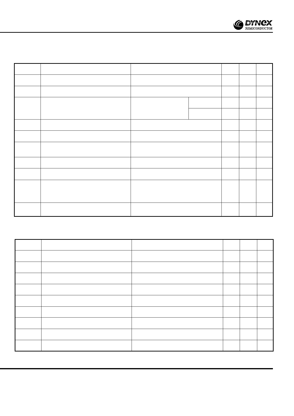
DYNAMIC CHARACTERISTICS
Symbol
Parameter
Conditions
Min. Max. Units
IRRM/IDRM
dV/dt
dI/dt
VT(TO)
rT
t
gd
IL
IH
tq
QS
Peak reverse and off-state current
At VRRM/VDRM, Tcase = 125oC
-
Maximum linear rate of rise of off-state voltage To 67% V T = 125oC.
-
DRM j
Rate of rise of on-state current
From 67% VDRM to 1000A, Repetitive 50Hz
-
Gate source 10V, 5Ω
tr ≤ 0.5µs. Tj = 125oC.
Non-repetitive -
Threshold voltage
At Tvj = 125oC
-
On-state slope resistance
Delay time
Latching current
At Tvj = 125oC
-
VD = 67% VDRM, Gate source 20V, 10Ω
Rise
time
0.5µs,
T
j
=
25oC
-
Tj = 25oC, VD = 20V.
-
Holding current
Tj = 25oC, VD = 5V, IT = 5A, ITM = 500A
30
Turn-off time
IT = 500A, tp = 1ms, Tj = 125˚C,
V
RM
=
100V,
dI /dt
RR
=
10A/µs,
500
dVDR/dt = 25V/µs to 3000V
Stored charge - triangular approximation
through IRR and 25% IRR
IT = 320A, -dIT/dt = 6A/µs
600
50 mA
1000 V/µs
50 A/µs
100 A/µs
1.6
V
3.5 mΩ
3.3
µs
1
A
120 mA
1200 µs
1500 µC
GATE TRIGGER CHARACTERISTICS AND RATINGS
Symbol
Parameter
Conditions
Typ. Max. Units
VGT
IGT
V
GD
VFGM
V
FGN
VRGM
I
FGM
PGM
P
G(AV)
Gate trigger voltage
Gate trigger current
Gate non-trigger voltage
Peak forward gate voltage
Peak forward gate voltage
Peak reverse gate voltage
Peak forward gate current
Peak gate power
Mean gate power
VDRM = 5V, Tcase = 25oC
VDRM = 5V, Tcase = 25oC
At V T = 125oC
DRM case
Anode positive with respect to cathode
-
3.0
V
-
300 mA
-
0.25 V
-
30
V
Anode negative with respect to cathode
-
0.25
V
-
5
V
Anode positive with respect to cathode
-
10
A
See Fig.8/9 Gate characteristics curves and table
-
100 W
-
5
W
4/10
www.dynexsemi.com
Share Link: 