MR850(2006) Ver la hoja de datos (PDF) - ON Semiconductor
Número de pieza
componentes Descripción
Fabricante
MR850 Datasheet PDF : 4 Pages
| |||
MR850, MR851, MR852, MR854, MR856
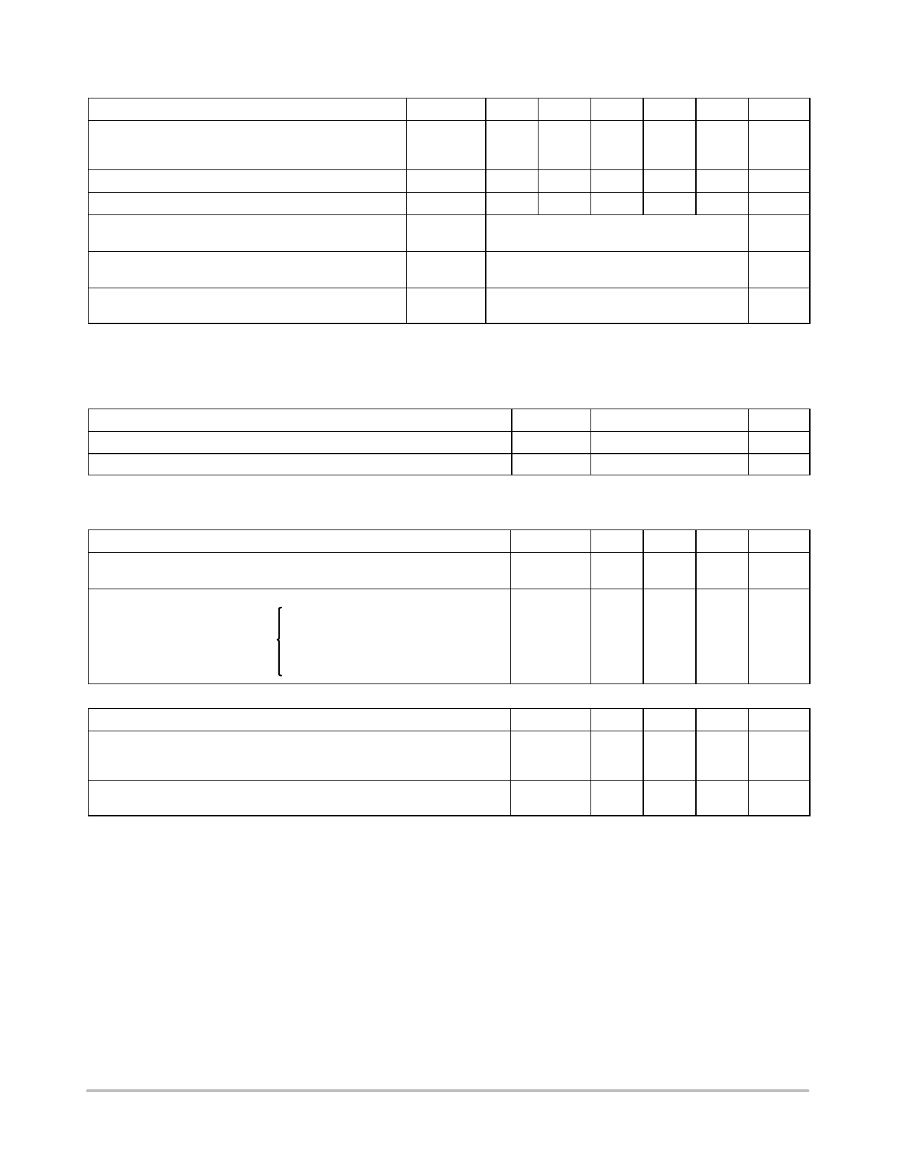
MAXIMUM RATINGS
Rating
Symbol MR850 MR851 MR852 MR854 MR856 Unit
Peak Repetitive Reverse Voltage
Working Peak Reverse Voltage
DC Blocking Voltage
Non−Repetitive Peak Reverse Voltage
RMS Reverse Voltage
Average Rectified Forward Current
(Single phase resistive load, TA = 80°C)
Non−Repetitive Peak Surge Current
(Surge Applied at Rated Load Conditions)
VRRM
50
100
200
400
600
V
VRWM
VR
VRSM
75
150
250
450
650
V
VR(RMS)
35
70
140
280
420
V
IO
3.0
A
IFSM
100
A
(one cycle)
Operating and Storage Junction Temperature Range
TJ, Tstg
− 65 to +125
°C
− 65 to +150
Stresses exceeding Maximum Ratings may damage the device. Maximum Ratings are stress ratings only. Functional operation above the
Recommended Operating Conditions is not implied. Extended exposure to stresses above the Recommended Operating Conditions may affect
device reliability.
THERMAL CHARACTERISTICS
Characteristic
Thermal Resistance, Junction−to−Ambient
(Recommended Printed Circuit Board Mounting)
Symbol
RqJA
Max
28
Unit
°C/W
ELECTRICAL CHARACTERISTICS
Characteristic
Forward Voltage
(IF = 3.0 A, TJ = 25°C)
Reverse Current (rated DC voltage) TJ = 25°C
MR850
MR851
TJ = 80°C
MR852
MR854
MR856
REVERSE RECOVERY CHARACTERISTICS
Characteristic
Reverse Recovery Time
(IF = 1.0 A to VR = 30 Vdc)
(IF = 15 A, di/dt = 10 A/ms)
Reverse Recovery Current
(IF = 1.0 A to VR = 30 Vdc)
Symbol
Min
Typ
Max
Unit
VF
−
1.04 1.25
V
IR
−
2.0
10
mA
−
−
150
−
60
150
−
−
200
−
−
250
−
100
300
Symbol
Min
Typ
Max
Unit
trr
ns
−
100
200
−
150
300
IRM(REC)
−
−
2.0
A
http://onsemi.com
2
Share Link: 