ML4435 Ver la hoja de datos (PDF) - Micro Linear Corporation
Número de pieza
componentes Descripción
Fabricante
ML4435 Datasheet PDF : 14 Pages
| |||
PRELIMINARY
ML4435
FUNCTIONAL DESCRIPTION
COMPONENT SELECTION
Selecting external components for the ML4435 requires
calculations based on the motor’s electrical and mechani-
cal parameters. The following is a list of the motor param-
eters needed to for these calculations:
The maximum DC motor supply voltage V MOTOR (V)
The maximum operating current I MAX (A)
The winding resistance measured line to line Rl-l Ω
The number of magnetic poles N (Unitless)
The Back EMF constant Ke (V s/RAD)
The torque constant Kτ (N m/A) of the motor (Kτ = Ke
in SI units)
The maximum speed of operation RPMMAX (RPM)
The moment of inertia J (Kg m2 ) of the motor and its
load
The viscous damping factor ζ (Unitless) of the motor and
its load
If one or more of the above values is not known, it is
still possible to pick components for the ML4435, but
some experimentation may be necessary to determine the
optimal values. All quantities are in SI units unless other-
wise specified. The following formulas and component
selection graphs should be considered as a starting point
from which to optimize the application. All calculations
for capacitors and resistors should be used as the first
approximation for selecting the closest standard value.
SUPPLY VOLTAGE AND ON-CHIP VOLTAGE
REFERENCE
VCC
The supply voltage at VCC (pin 10) is nominally
12V ± 10%. A bypass capacitor of 0.1µF to ground as
close as possible to VCC (pin 10) is recommended.
RT
An internal 6V reference is generated inside the ML4435.
The reference appears on RT (pin 6). A resistor to ground
on RT sets the PWM frequency. This resistor can be
replace with a potentiomenter for use in setting the speed
command. This topic is discussed under the PWM SPEED
CONTROL section. Note: Buffer this pin with an op amp
with at least a 1MΩ input impedance if external circuits
are necessary.
OUTPUT DRIVERS
The output drivers LA, LB, LC, HA, HB, and HC provide
totem pole output drive signals for a 3 phase bridge power
stage. All control functions in the ML4435 translate to
outputs at these pins. LA, LB, LC provide the low side drive
signals for phases A, B, and C of the 3 phase power stage
and are 12V active high signals. HA, HB, and HC provide
the high side signals for phases A, B, and C of the 3 phase
power stage and are 12V active low signals.
CURRENT LIMITING IN THE 3 PHASE BRIDGE
POWER STAGE
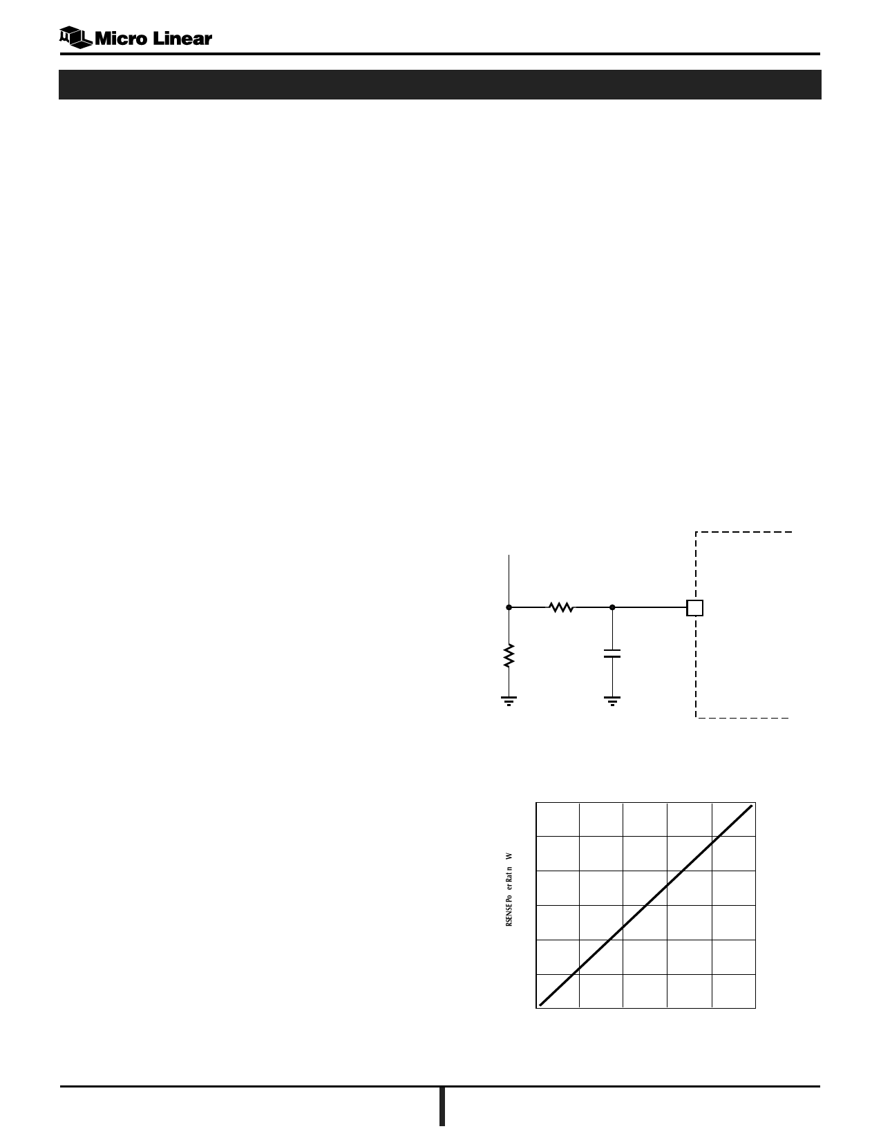
A current sense resistor RSENSE shown in Figure 1 is
installed in the 3 phase power stage to regulate the maxi-
mum current in the power stage and the BLDC motor.
Current regulation is accomplished by shutting off the
output drivers LA, LB, and LC for the remainder of the
PWM period if the voltage across RSENSE exceeds the
current limit threshold set by the SOFT START (pin 19).
The maximum power dissipated in RSENSE is shown in
Figure 2.
R
RSENSE
C
ISENSE
Figure 1. Current Limit with RSENSE
6
5
4
3
2
0
0
2
4
6
0
IMAX [MOTOR] A
Figure 2. RSENSE Power vs. Motor Current
May, 2000 PRELIMINARY DATASHEET
5
Share Link: 