MICRF102 Ver la hoja de datos (PDF) - Micrel
Número de pieza
componentes Descripción
Fabricante
MICRF102 Datasheet PDF : 12 Pages
| |||
MICRF102
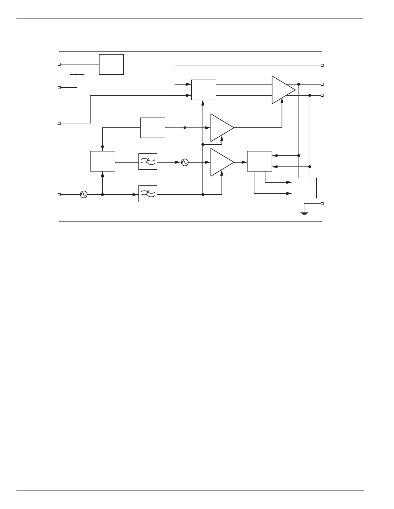
Block Diagram
Micrel
STBY
VDD
VDD
Reference
Bias
(10)
TX
Bias
Control
(9)
Power
Amp
(8)
ASK
ANTP
ANTM
PC
Phase
Detector
(2)
REF.OSC
Reference
Oscillator (1)
Prescaler
Divide
by 32
(5)
VCO (4)
(3)
Buffer
(6a)
Buffer
(6b)
Antenna
Tuning
Control
(7)
Varactor
Device
(11)
VSS
Functional Description
The block diagram illustrates the basic structure of the
MICRF102. Identified in the figure are the principal functional
blocks of the IC, namely the (1, 2, 3, 4, 5) UHF Synthesizer,
(6a/b) Buffer, (7) Antenna tuner, (8) Power amplifier, (9) TX
bias control, (10) Reference bias and, (11) Process tuner.
The UHF synthesizer generates the carrier frequency with
quadrature outputs. The in-phase signal (I) is used to drive
the PA and the quadrature signal (Q) is used to compare the
antenna signal phase for antenna tuning purposes.
The Antenna tuner block senses the phase of the transmit
signal at the antenna port and controls the varactor capacitor
to tune the antenna.
The Power control unit senses the antenna signal and con-
trols the PA bias current to regulate the antenna signal to
the transmit power.
The Process tune circuit generates process independent bias
currents for different blocks.
A PCB antenna loop coupled with a resonator and a resistor
divider network are all the components required to construct
a complete UHF transmitter for remote actuation applications
such as automotive keyless entry.
Included within the IC is a differential varactor that serves
as the tuning element to insure that the transmit frequency
and antenna are aligned with the receiver over all supply and
temperature variations.
MICRF102
6
December 2006
Share Link: 