IXTH10P60(2001) Ver la hoja de datos (PDF) - IXYS CORPORATION
Número de pieza
componentes Descripción
Fabricante
IXTH10P60 Datasheet PDF : 2 Pages
| |||
ADVANCE TECHNICAL INFORMATION
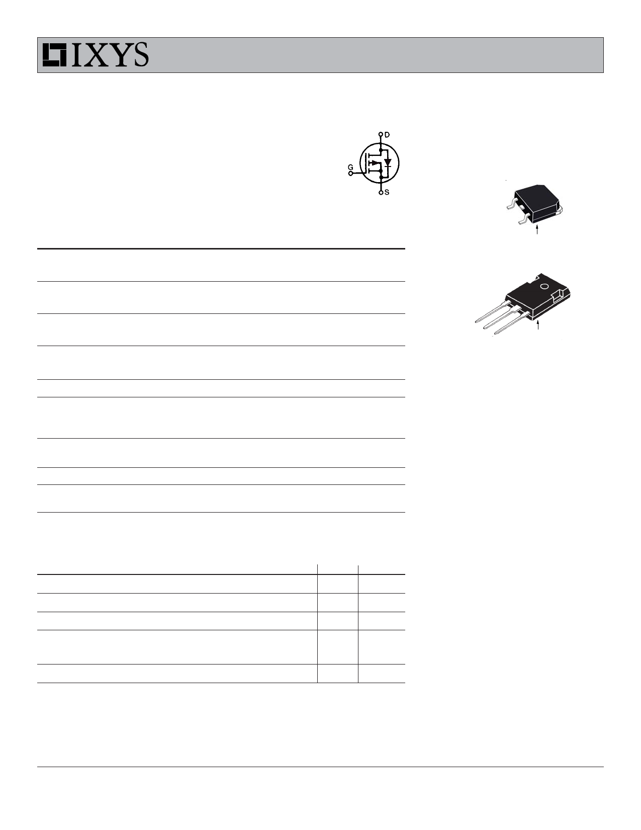
Standard Power MOSFET
P-Channel Enhancement Mode
Avalanche Rated
IXTH 10P60 VDSS = -600 V
ID25 = -10 A
RDS(on) =
1Ω
Symbol
V
DSS
V
DGR
VGS
VGSM
ID25
IDM
IAR
EAR
PD
TJ
T
JM
T
stg
TL
Md
Weight
Test Conditions
TJ = 25°C to 150°C
TJ = 25°C to 150°C; RGS = 1 MΩ
Continuous
Transient
TC = 25°C
TC = 25°C, pulse width limited by TJ
TC = 25°C
TC = 25°C
TC = 25°C
Maximum lead temperature for soldering
1.6 mm (0.062 in.) from case for 10 s
Mounting torque
Maximum Ratings
-600
V
-600
V
±20
V
±30
V
-10
A
-40
A
-10
A
30
mJ
300
W
-55 ... +150
°C
150
°C
-55 ... +150
°C
300
°C
1.13/10 Nm/lb.in.
6
g
TO-247 AD
D (TAB)
G = Gate,
S = Source,
D = Drain,
TAB = Drain
Features
• International standard package
JEDEC TO-247 AD
• Low RDS (on) HDMOSTM process
• Rugged polysilicon gate cell structure
• Unclamped Inductive Switching (UIS)
rated
• Low package inductance (<5 nH)
- easy to drive and to protect
Symbol
V
DSS
VGS(th)
IGSS
IDSS
RDS(on)
Test Conditions
VGS = 0 V, ID = -250 µA
VDS = VGS, ID = -250 µA
VGS = ±20 VDC, VDS = 0
VDS = 0.8 VDSS
VGS = 0 V
VGS = -10 V, ID = 0.5 ID25
Characteristic Values
(TJ = 25°C, unless otherwise specified)
min. typ. max.
-600
-3.0
TJ = 25°C
TJ = 125°C
V
-5.0 V
±100 nA
-25 µA
-1 mA
1.0 Ω
Applications
• High side switching
• Push-pull amplifiers
• DC choppers
• Automatic test equipment
Advantages
• Easy to mount with 1 screw
(isolated mounting screw hole)
• Space savings
• High power density
© 2001 IXYS All rights reserved
98849 (8/01)
Share Link: 