HV9906X Ver la hoja de datos (PDF) - Supertex Inc
Número de pieza
componentes Descripción
Fabricante
HV9906X Datasheet PDF : 10 Pages
| |||
Functional Description
The HV9906 consists of the following functional blocks:
High Voltage Regulator
Bandgap Reference
Under Voltage Lockout and Power On Reset
Voltage Controlled Oscillator
Feed Forward On Time Control
Differential Sense Circuit and Programmable Reference
Integrator
Sample and Hold VCO Control
Gate Driver
Soft Start
The following sections provide a detailed explanation of each of
these blocks.
High Voltage Regulator
All internal circuits operate from a nominal 10V VDD supply
provided by an onboard linear regulator capable of accepting input
voltages up to 400V. This regulator blocks reverse current flow
from VDD to +VIN, such as in the case when the input voltage is a
full wave rectified sine wave. Therefore, if a sufficiently large
bypass capacitor (>1µF) is connected to VDD, the operation of the
circuit can be maintained during the times when the full wave
rectified input voltage is less than the regulated output voltage.
High operating frequency and high input voltage applications will
result in increased power dissipation in the regulator. For these
applications efficiency may be improved by bootstrapping the VDD
pin if a non-isolated +10V output is available. Supertex’s high
voltage technology allows a very low current regulator, rather than
a shunt, to power the IC. This makes it possible to continuously
operate the IC from the AC line, within thermal limits & without
bootstrapping, in certain applications.
Bandgap Reference
As the regulator turns on and the VDD voltage rises, a bandgap
reference is activated to establish the regulation point of the
regulator and provide the required references for the internal
circuits. The references are strictly internal and not available at
any pin of the device.
Under Voltage Lockout and Power On Reset
On initial power application the high input voltage (up to 400V)
linear regulator charges the capacitor connected to VDD and seeks
to provide a stable supply for the internal circuitry. Under voltage
lockout (UVLO) holds the voltage controlled oscillator (VCO)
disabled until the VDD supply rises above a nominal 8.5V and
power on reset (POR) clamps the capacitors in the sample and
hold and integrator circuits low for a short time thereafter, thus
setting the VCO to its lowest frequency state. The UVLO has a
0.5V hysteresis to prevent false triggering due to ripple on VDD.
Voltage Controlled Oscillator
The period of the voltage controlled oscillator (VCO) is determined
by the output of the sample and hold circuit while the feed forward
control from the VON pin provides fast direct control of the oscillator
output on time. For unusual operating circumstance the VCO may
be driven to its maximum frequency and the on time may exceed
the period of the oscillator. This will cause cycle skipping or an
effective reduction in output frequency by an integer factor.
HV9906
Feed Forward On Time Control
The output signal to the gate driver is controlled by a latch that is
set by the output of the VCO and reset by the feed forward on time
control, thus the voltage applied to the VON pin provides direct and
continuous control of the gate drive on time. The on time is
inversely proportional to the applied voltage and there is an
internally set limit to the maximum on time (17.8µS) so that 0V will
not result in an infinite on time. Refer to “Programming On Time”
in the Design Information section.
To operate in discontinuous conduction mode with constant energy
transfer per cycle a resistor divider from the input voltage is
connected to the VON pin, thereby providing fast feed forward input
regulation control. This control loop can easily track a rectified
sine wave of input voltage at 50Hz, 60Hz or 400Hz provided that
the capacitor connected at VDD can store sufficient energy to
prevent decay below the UVLO threshold during the time when the
rectified sine wave input voltage at +VIN is below 10V. For a 100V
50Hz rectified sine wave a 3.3µF capacitor connected to VDD is
sufficient to guarantee stable operation.
For power factor correction applications an input voltage peak
detector or a low pass filter can be used to drive the VON pin. This
will provide an essentially constant on time control voltage
resulting in an energy transfer per oscillator cycle directly
proportional to the input voltage.
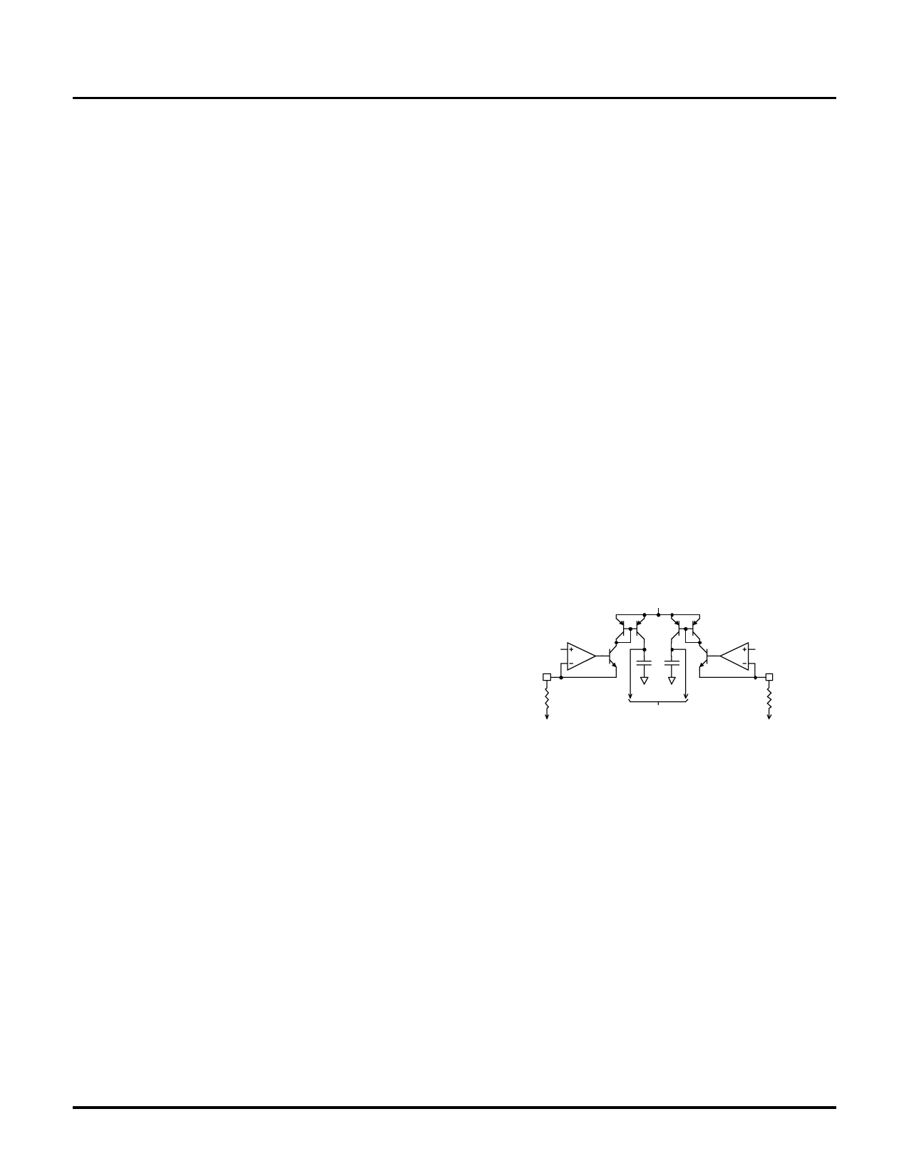
Differential Sense Circuit and Programmable Reference
The following simplified equivalent circuit is provided to clarify the
operation and programming of this circuit.
Vdd
+1V
PS
R PS
To Least Negative
Sense Node
Relative to +1 Volt
20pF
To Sample and Hold
Comparators
+1V
NS
RNS
To Most Negative
Sense Node
Relative to +1Volt
This differential sense circuit is typically used to monitor the output
voltage or current of a power converter. The circuit operates by
sourcing current (typically 5µA) from both the PS and NS pins
which are regulated at a nominal +1V and the control loop seeks to
maintain a sense node voltage (voltage across a current sense
resistor or the voltage across a resistor divider) that will make the
NS and PS currents equal. Regulation is established when there
is zero current difference in the PS and NS pins. This differential
common mode sense method reduces noise sensitivity and
enables the user to define the magnitude of the sensed voltage
(i.e. +100mV for high efficiency or –2.5V to escape the noise floor)
and thus the effective reference, provided the sensed nodes are at
less than +1V with respect to ground.
4
07/23/02
Supertex, Inc. 1235 Bordeaux Drive, Sunnyvale, CA 94089 TEL: (408) 744-0100 FAX: (408) 222-4895 www.supertex.com
Share Link: 