MCP6234 Ver la hoja de datos (PDF) - Microchip Technology
NĂșmero de pieza
componentes DescripciĂłn
Fabricante
MCP6234 Datasheet PDF : 40 Pages
| |||
MCP6231/1R/1U/2/4
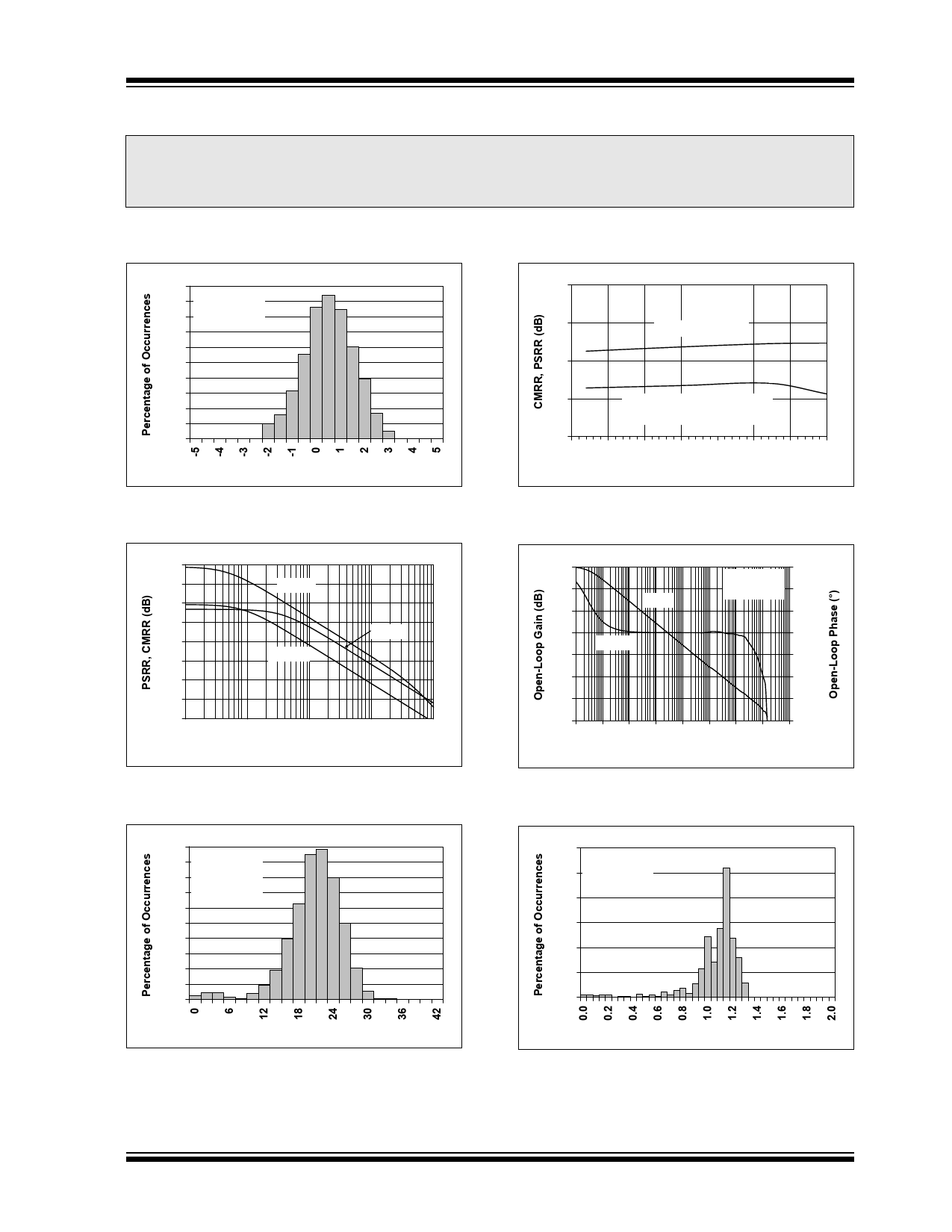
2.0 TYPICAL PERFORMANCE CURVES
Note:
The graphs and tables provided following this note are a statistical summary based on a limited number of
samples and are provided for informational purposes only. The performance characteristics listed herein
are not tested or guaranteed. In some graphs or tables, the data presented may be outside the specified
operating range (e.g., outside specified power supply range) and therefore outside the warranted range.
Note: Unless otherwise indicated, TA = +25°C, VDD = +1.8V to +5.5V, VSS = GND, VCM = VDD/2, VOUT â VDD/2,
RL = 100 kΩ to VDD/2 and CL = 60 pF.
20%
18%
16%
14%
12%
10%
8%
6%
4%
2%
0%
630 Samples
VCM = VSS
Input Offset Voltage (mV)
FIGURE 2-1:
Input Offset Voltage.
90
85
PSRR (VCM = VSS)
80
75
70
-50
CMRR (VCM = -0.3V to +5.3V,
VDD = 5.0V)
-25 0 25 50 75 100 125
Ambient Temperature (°C)
FIGURE 2-4:
Temperature.
CMRR, PSRR vs. Ambient
100
90
80
70
60
50
40
30
20 1.E+01
10
PSRR-
PSRR+
CMRR
1.E+02
100
1.E+03
1k
Frequency (Hz)
1.E+04
10k
1.E+05
100k
FIGURE 2-2:
Frequency.
PSRR, CMRR vs.
120
0
RL = 10 kâŠ
100
VCM = VDD/2 -30
Gain
80
-60
60
Phase
40
-90
-120
20
-150
0
-180
-20
-210
10..E1- 1.1E+ 11.E0+ 11.0E0+ 11.Ek+ 11.0Ek+ 110.E0+k 11.EM+ 1.0EM+
01 00 01 Fr0e2que0n3cy (0H4z) 05 06 07
FIGURE 2-5:
Frequency.
Open-Loop Gain, Phase vs.
20%
18%
16%
14%
12%
10%
8%
6%
4%
2%
0%
630 Samples
VCM = VDD/2
TA = +85°C
Input Bias Current (pA)
FIGURE 2-3:
Input Bias Current at +85°C.
30%
25%
20%
632 Samples
VCM = VDD/2
TA = +125°C
15%
10%
5%
0%
FIGURE 2-6:
+125°C.
Input Bias Current (nA)
Input Bias Current at
© 2009 Microchip Technology Inc.
DS21881E-page 5
Share Link: 