MC74VHC1G32DFT1 Ver la hoja de datos (PDF) - E-Tech Electronics LTD
Número de pieza
componentes Descripción
Fabricante
MC74VHC1G32DFT1 Datasheet PDF : 4 Pages
| |||
MC74VHC1G32
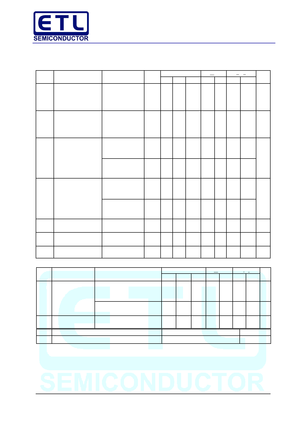
DC ELECTRICAL CHARACTERISTICS
V CC
T A = 25°C
T A < 85°C –55°C<TA<125°C
Symbol Parameter
Test Conditions (V) Min Typ Max Min Max Min Max Unit
V IH
Minimum High–Level
2.0 1.5
1.5
1.5
V
Input Voltage
3.0 2.1
2.1
2.1
4.5 3.15
3.15
3.15
5.5 3.85
3.85
3.85
V IL
Maximum Low–Level
2.0
0.5
0.5
0.5 V
Input Voltage
3.0
0.9
0.9
0.9
4.5
1.35
1.35
1.35
5.5
1.65
1.65
1.65
V OH Minimum High–Level V IN = V IH or V IL
2.0 1.9 2.0
1.9
1.9
V
Output Voltage
I OH = – 50 µA
3.0 2.9 3.0
2.9
2.9
V IN = V IH or V IL
4.5 4.4 4.0
4.4
4.4
V IN = V IH or V IL
I OH = –4 mA
3.0 2.58
2.48
2.34
I OH = –8 mA
4.5 3.94
3.80
3.66
V OL Maximum Low–Level
V IN = V IH or V IL
2.0
0.0 0.1
0.1
0.1 V
Output Voltage
I OL = 50 µA
3.0
0.0 0.1
0.1
0.1
V IN = V IH or V IL
4.5
0.0 0.1
0.1
0.1
V IN = V IH or V IL
I OL = 4 mA
3.0
0.36
0.44
0.52
I IN Maximum Input
I OL = 8 mA
4.5
V IN = 5.5 V or GND 0 to5.5
0.36
0.44
0.52
±0.1
±1.0
±1.0 µA
Leakage Current
I CC Maximum Quiescent V IN = V CC or GND 5.5
2.0
20
40 µA
Supply Current
AC ELECTRICAL CHARACTERISTICS C load = 50 pF, Input t r = t f = 3.0 ns
Symbol Parameter
Test Conditions
T A = 25°C
T A < 85°C –55°C<TA<125°C
Min Typ Max Min Max Min Max Unit
t PLH , Maximum
V CC = 3.3± 0.3 V C L = 15 pF
4.8 7.9
9.5
11.5 ns
t PHL Propagation Delay,
Input A or B to Y
C L = 50 pF
6.1 11.4
13.0
15.5
V CC = 5.0± 0.5 V C L = 15 pF
3.7 5.5
6.5
8.0
C L = 50 pF
4.4 7.5
8.5
10.0
C IN Maximum Input
5.5 10
10
10 pF
Capacitance
Typical @ 25°C, V CC = 5.0 V
C PD
Power Dissipation Capacitance (Note 6)
11
pF
6. C PD is defined as the value of the internal equivalent capacitance which is calculated from the operating current consumption without
. load. Average operating current can be obtained by the equation: I CC(OPR) = C PD • V CC • f in + I CC C PD is used to determine the no–
load dynamic
power consumption; P D = C PD
•
V
2
CC
•
f in + I CC •
V CC .
VH32–3/4
Share Link: 