MC1455 Ver la hoja de datos (PDF) - ON Semiconductor
Número de pieza
componentes Descripción
Fabricante
MC1455 Datasheet PDF : 11 Pages
| |||
MC1455, MC1455B, NCV1455B
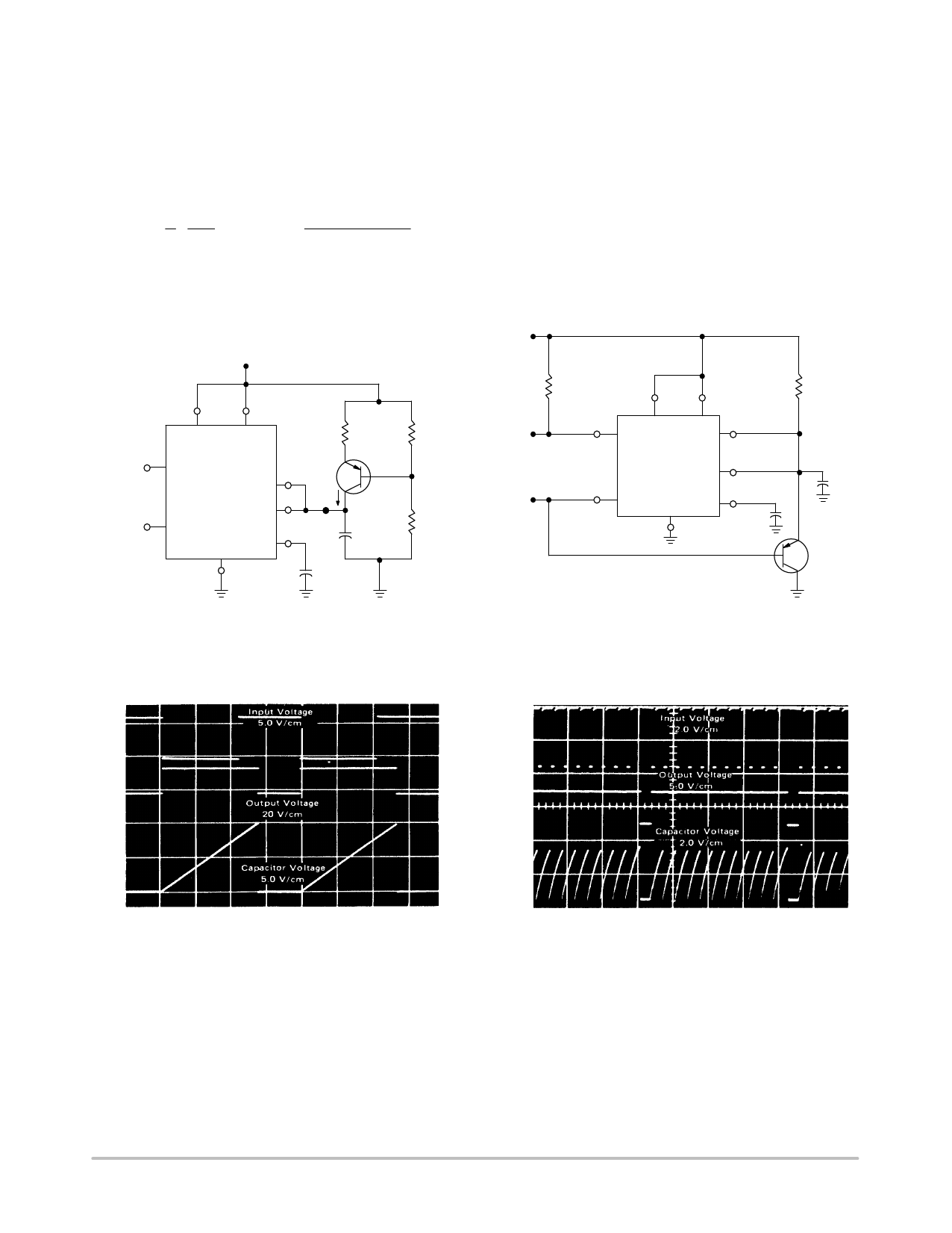
APPLICATIONS INFORMATION
Linear Voltage Ramp
In the monostable mode, the resistor can be replaced by a
constant current source to provide a linear ramp voltage. The
capacitor still charges from 0 VCC to 2/3 VCC. The linear
ramp time is given by:
t = 2 VCC , where I = VCC − VB − VBE
31
RE
If VB is much larger than VBE, then t can be made
independent of VCC.
Missing Pulse Detector
The timer can be used to produce an output when an input
pulse fails to occur within the delay of the timer. To
accomplish this, set the time delay to be slightly longer than
the time between successive input pulses. The timing cycle
is then continuously reset by the input pulse train until a
change in frequency or a missing pulse allows completion of
the timing cycle, causing a change in the output level.
+VCC (5.0 V to 15 V)
VCC
Reset 4 8 VCC
Digital 3
Output
MC1455
RE 2N4403 R1
7
VE
or Equiv
VB
I
6
2
Trigger
5
Sweep
Output
C
R2
1 0.01 mF Control
Voltage
RL
3
Output
Input
2
Trigger
Reset
4
VCC
8
Discharge
MC1455
1
7
Threshold
6 Control
5 Voltage
0.01 mF
RA
C
2N4403
or Equiv
Figure 20. Linear Voltage Sweep Circuit
Figure 21. Missing Pulse Detector
t = 100 ms/cm
(RE = 10 kW, R2 = 100 kW, R1 = 39 kW, C = 0.01 mF, VCC = 15 V)
Figure 22. Linear Voltage Ramp Waveforms
t = 500 ms/cm
(RA = 2.0 kW, RL = 1.0 kW, C = 0.01 mF, VCC = 15 V)
Figure 23. Missing Pulse Detector Waveforms
http://onsemi.com
7
Share Link: 