MC13077 Ver la hoja de datos (PDF) - Motorola => Freescale
Número de pieza
componentes Descripción
Fabricante
MC13077 Datasheet PDF : 14 Pages
| |||
MC13077
Chroma Encoding
Modulation of the color difference components is
performed by two double–balanced mixers that are driven
from quadrature signals provided by an internal ring counter.
The quadrature signals are derived from a ring counter that is
driven by the 4x oscillator, and which makes highly accurate
quadrature angles possible.
If PAL encoding is selected, negative burst flag envelope
is provided to both B–Y and R–Y components equally, then
the R–Y envelope phase is switched positive and negative
from line–to–line to provide the PAL alternating burst phase
characteristic. An internal flip–flop that provides the internal
fH/2 switching is enabled by opening the connection at
Pin 19. If enabled, the pin will exhibit the internally generated
half line frequency squarewave. If it is desired to reverse the
sense of the PAL swinging burst, it can be done at this pin by
pulling Pin 19 low when the squarewave is high. The
component envelopes with the proper PAL burst phase are
then modulated to produce the composite chroma.
If the MC13077 is encoding to NTSC, only the B–Y color
difference component is provided a negative burst flag. This
envelope when modulated results in the characteristic –180°
phase difference between the color burst and the subcarrier
for the B–Y component. Pin 19 should be grounded for NTSC
operation to disable the PAL flip–flop.
Video Outputs
After being filtered, the composite chroma is recombined
with the composite luma information for the Composite Video
output. The composite chroma and composite luma
components are also kept separate and buffered for the
chroma S–Video and luma S–Video outputs. The video
outputs are provided with low impedance emitter–follower
stages and, therefore, require an external 75 Ω impedance
determining series resistor (see Figure 7). The outputs are
designed to drive a 75 Ω load through the external 75 Ω
series resistor.
The Composite Video output will provide 1.23 Vpp of video
(sync tip–to–peak chroma) for 100% saturated video at the
75 Ω load. Luma S–Video will be 1.0 Vpp (sync tip–to–peak
white) at the 75 Ω load and the Chroma S–Video output will
provide 885 mVpp at the 75 Ω load.
Figure 7. Composite S–Luma and
S–Chroma Video Outputs
MC13077
1.0 kΩ
75 Ω
Zo = 75 Ω
75 Ω
APPLICATIONS INFORMATION
Figures 8 through 13 are application examples showing
the versatility of the MC13077.
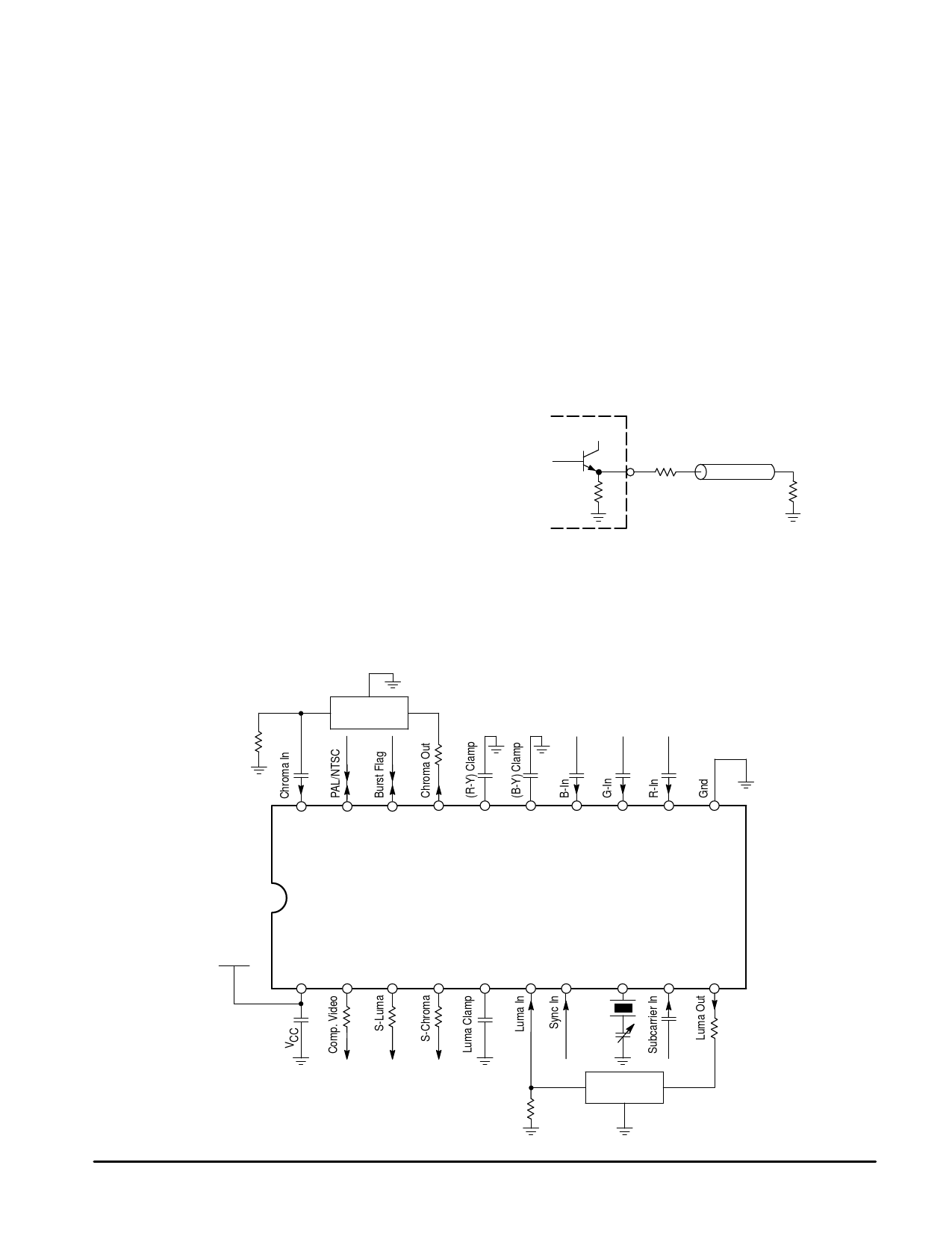
Figure 8. Standard Encoder Application with RGB Inputs and Phase–Locked Subcarrier
Chroma
Bandpass
1.1 k
4.7 n
1.0
k
10 n 10 n 1.0 µ 1.0 µ 1.0 µ
20
19
18
17
16
15
14
13
12
11
MC13077
+5.0 V
1
1.0 µF
2
3
4
5
6
75
75
75
10 n
7
8
14.32/
17.73
20 p
9
10
1.0 n 1.2 k
Luma Delay
1.2 k
MOTOROLA ANALOG IC DEVICE DATA
9
Share Link: 