MC10H352 Ver la hoja de datos (PDF) - ON Semiconductor
Número de pieza
componentes Descripción
Fabricante
MC10H352 Datasheet PDF : 6 Pages
| |||
MC10H352
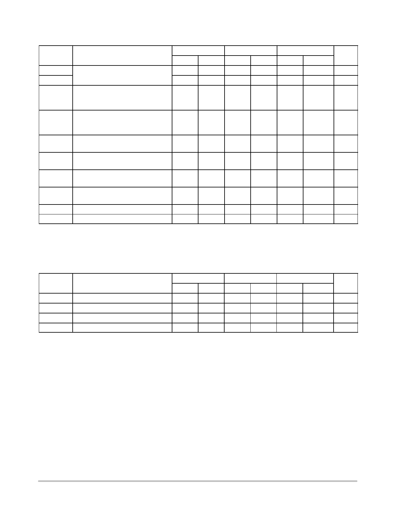
Table 2. ELECTRICAL CHARACTERISTICS (VCC = VCC1 = VCC2 = 5.0 V ± 5.0%) (Note 1)
0°
25°
75°
Symbol
Characteristic
Min
Max
Min
Max
Min
Max
Unit
ECL
Power Supply
TTL
Current
50
45
20
15
50
mA
20
mA
IR
Reverse Current
Pins 7, 8, 12, 14
Pin 9
25
20
100
80
mA
25
100
IF
Forward Current
Pins 7, 8, 12, 14
Pin 9
−0.8
−0.6
−3.2
−2.4
mA
−0.8
−3.2
V(BR)in
Input Voltage
Breakdown
5.5
5.5
5.5
Vdc
VI
Input Clamp Voltage
(Iin = −18 mA)
VOH
High Output
Voltage (Note 2)
−1.5
−1.5
−1.5
Vdc
3.98
4.16
4.02
4.19
4.08
4.27
Vdc
VOL
Low Output
Voltage (Note 2)
3.05
3.37
3.05
3.37
3.05
3.37
Vdc
VIH
High Input Voltage
3.15
3.15
3.15
Vdc
VIL
Low Input Voltage
1.5
1.5
1.5
Vdc
*Positive Emitter Coupled Logic
1. Each MECL 10H™ series circuit has been designed to meet the dc specifications shown in the test table, after thermal equilibrium has been
established. The circuit is in a test socket or mounted on a printed circuit board and transverse air flow greater than 500 lfpm is maintained.
Outputs are terminated through a 50 W resistor to VCC − 2.0 Vdc.
2. With VCC at 5.0 V. VOH/VOL change 1:1 with VCC.
Table 3. AC PARAMETERS
0°
25°
75°
Symbol
Characteristic
Min
Max
Min
Max
Min
Max
Unit
tpd
Propagation Delay (Note 3)
tr
Rise Time (20% to 80%)
tf
Fall Time (80% to 20%)
fmax
Maximum Operating Frequency
0.4
1.9
0.4
2.0
0.4
0.4
1.9
0.4
2.0
0.4
0.4
1.9
0.4
2.0
0.4
150
150
150
2.1
ns
2.1
ns
2.1
ns
MHz
NOTE: Device will meet the specifications after thermal equilibrium has been established when mounted in a test socket or printed circuit
board with maintained transverse airflow greater than 500 lfpm. Electrical parameters are guaranteed only over the declared
operating temperature range. Functional operation of the device exceeding these conditions is not implied. Device specification limit
values are applied individually under normal operating conditions and not valid simultaneously.
3. Propagation delay is measured on this circuit from VCC/2 on the input waveform to the 50% point on the output waveform.
http://onsemi.com
3
Share Link: 