MC-7834-KC Ver la hoja de datos (PDF) - NEC => Renesas Technology
Número de pieza
componentes Descripción
Fabricante
MC-7834-KC Datasheet PDF : 2 Pages
| |||
NEC's 870 MHz GaAs CATV MC-7834-KC
20 dB PUSH-PULL AMPLIFIER
FEATURES
• GaAs ACTIVE DEVICES
• LOW DISTORTION
• HIGH LINEAR GAIN:
MC-7834-KC - GL = 21 dB MIN at f = 870 MHz
• LOW RETURN LOSS
• LOW GAIN CHANGE OVER TEMPERATURE
• SPECIFIED FOR 79, 110, and 132 CHANNELS
PERFORMANCE
• HIGH RELIABILITY AND RUGGEDNESS:
Withstands environmental extremes as well as Silicon
devices (Surge, ESD, Etc.)
DESCRIPTION
NEC's MC-7834-KC is a GaAs Multi-Chip Module designed
for use as input stages in CATV applications up to 870 MHz.
Because this unit is a GaAs device, it has low distortion, low
noise figure, and low return loss across the entire frequency
band. The MC-7834-KC is similar to NEC's standard push-pull
devices, but with the higher current allows better distortion
performance, especially X-Mod.
Like the previous generation of products, these devices sur-
vive such hazards as surge and ESD as well as their silicon
competitors, but deliver superior performance with low DC
current required.
All devices are assembled and tested using fully automated
equipment to maximize consistency in part to part perfor-
mance, and reliability is assured by NEC's stringent quality
and process control procedures. These parts come in industry
compatible hybrid packages.
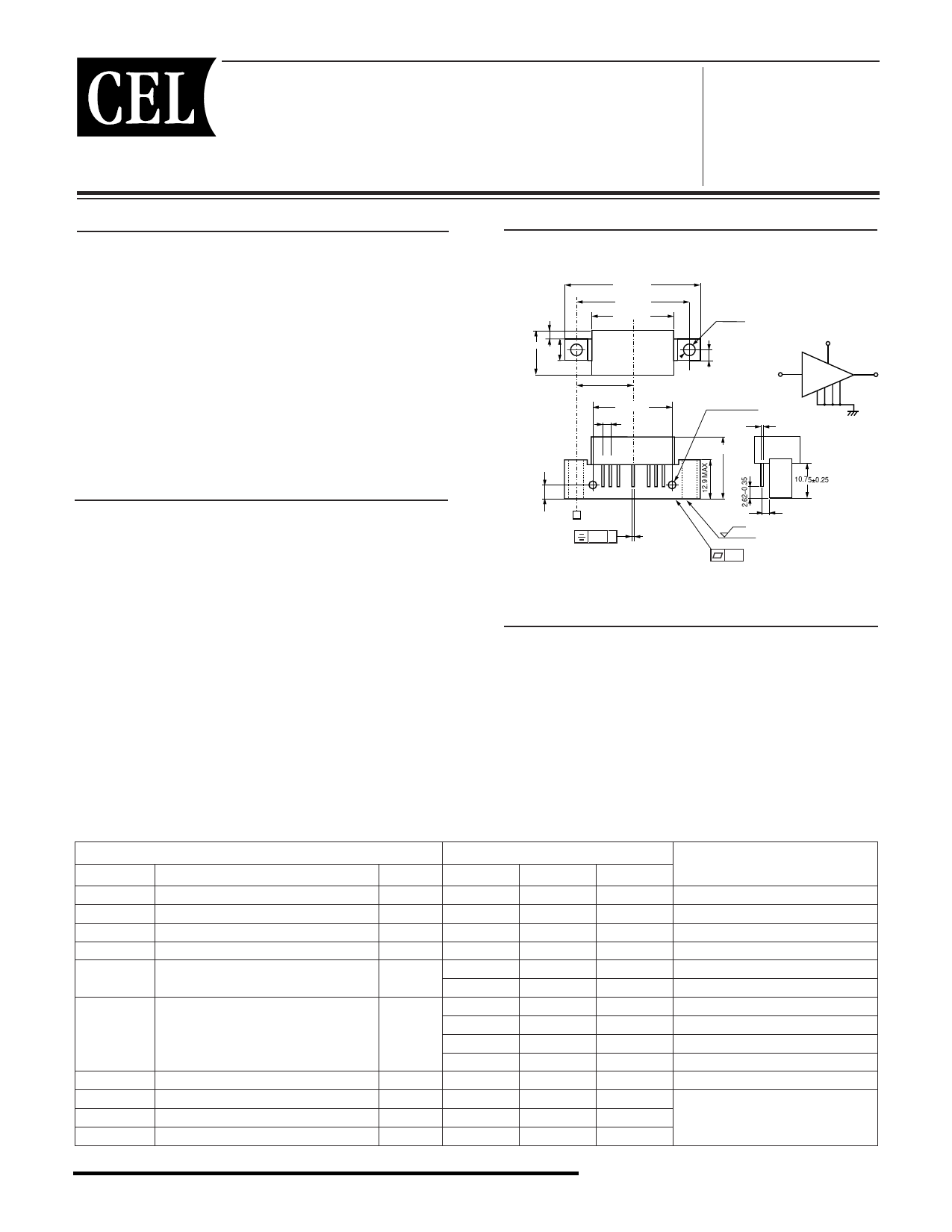
OUTLINE DIMENSIONS (Units in mm)
PACKAGE OUTLINE H02
3.2 MAX
14.85 MAX
8.1 MAX
45.08 MAX
38.1±0.25
27.5 MAX
19.05±0.38
25.4±0.25
2.54±0.25
12 3 5 789
4.25
+
-
0.25
0.35
4.0±0.25
6-32 unc 2B
21.5 MAX
VDD
5
1
9
In
Out
2 378
0.51±0.050
Gnd
10.75±0.25
4.19±0.13 A
0.38.. A
6.3 2.5
±0.05
2.54±0.38
APPLICATIONS
• CATV HEADEND SYSTEMS
• CATV OPTICAL NODES
• CATV DISTRIBUTION AMPS
ELECTRICAL CHARACTERISTICS (TA = 30±5 °C, VDD = 24 V, ZS = ZL = 75 Ω)
SYMBOLS
PART NUMBER
CHARACTERISTICS
UNITS
MC-7834-KC
MIN
TYP
MAX
TEST CONDITIONS
BW
Frequency Range
GL
Linear Gain
S
Gain Slope
Gf
Gain Flatness
Noise Figure 1
NF
Noise Figure 2
RL
Input/Output Return Loss
IDD
CTB
XMod
CSO
Operating Current
Composite Triple Beat
Cross Modulation
Composite Second Order
MHz
50
–
870
dB
20.0
–
21.0 f = 870 MHz
dB
0.2
–
1.0
f = 40 to 870 MHz
dB
–
–
0.7
40 to 870 MHz; Peak to Valley
dB
–
–
6.5
f = 50 MHz
–
–
7.0
f = 870 MHz
dB
20.0
–
–
40 to 160MHz
19.0
–
–
160 to 320 MHz
17.5
–
–
320 to 640 MHz
16.0
–
–
640 to 870 MHz
mA
180
–
325
RF OFF
dBc
–
–
-59
f = 40 to 870 MHz; 110 Channels,
dBc
–
–
-52
VOUT = 44 dBmV, Flat
dBc
–
–
-59
California Eastern Laboratories
Share Link: 