MBRM120L Ver la hoja de datos (PDF) - ON Semiconductor
Número de pieza
componentes Descripción
Fabricante
MBRM120L Datasheet PDF : 5 Pages
| |||
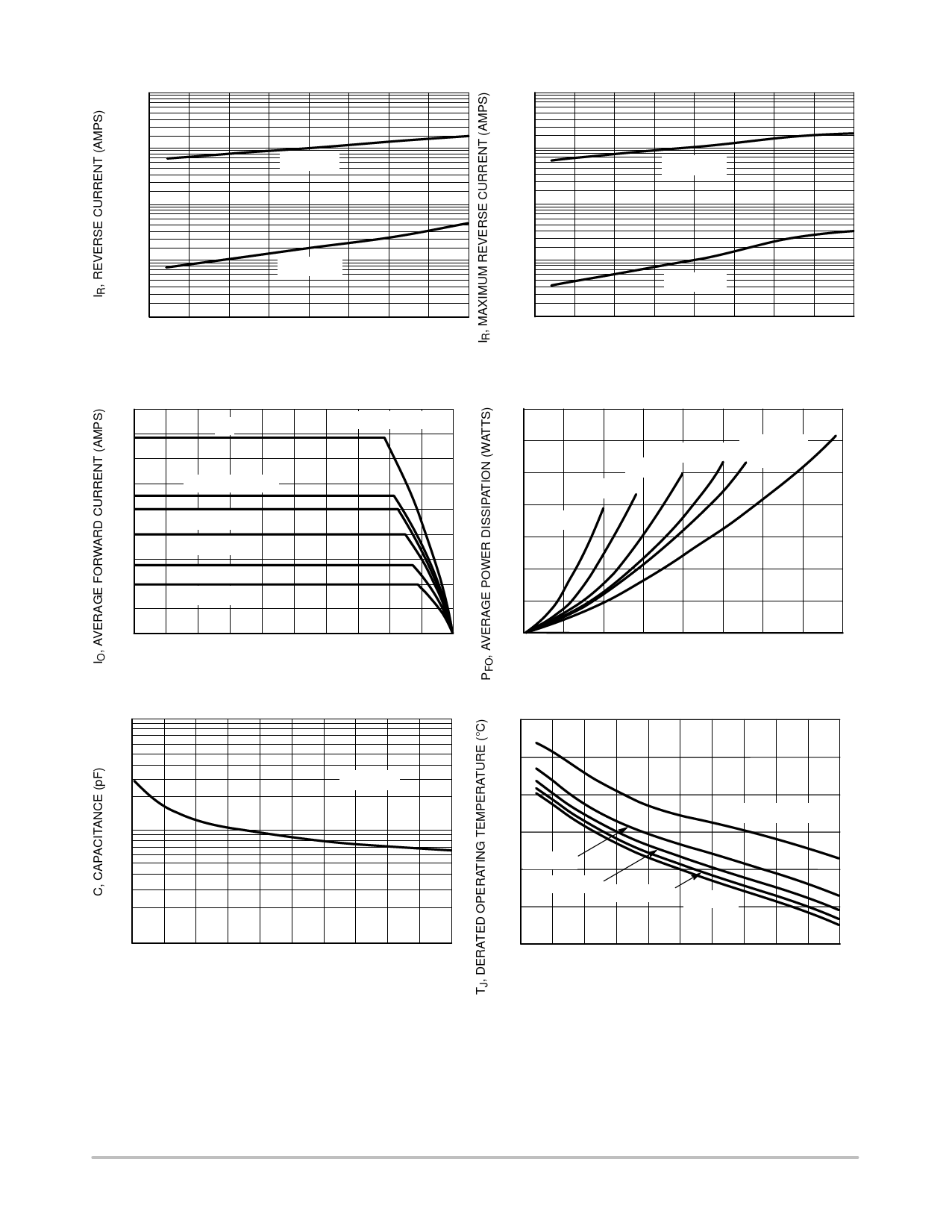
10E−3
1.0E−3
100E−6
TJ = 85°C
MBRM120L
100E−3
10E−3
1.0E−3
TJ = 85°C
10E−6
1.0E−6
0
TJ = 25°C
5.0
10
15
VR, REVERSE VOLTAGE (VOLTS)
Figure 3. Typical Reverse Current
100E−6
10E−6
20
0
TJ = 25°C
5.0
10
15
20
VR, REVERSE VOLTAGE (VOLTS)
Figure 4. Maximum Reverse Current
1.8
1.6
dc
FREQ = 20 kHz
1.4
1.2
SQUARE WAVE
1.0
Ipk/Io = p
0.8
Ipk/Io = 5
0.6
0.4
Ipk/Io = 10
Ipk/Io = 20
0.2
0
25 35 45 55 65 75 85 95 105 115 125
TL, LEAD TEMPERATURE (°C)
Figure 5. Current Derating
0.7
0.6
SQUARE
0.5
Ipk/Io = p
Ipk/Io = 5
WAVE
dc
Ipk/Io = 10
0.4
Ipk/Io = 20
0.3
0.2
0.1
0
0 0.2 0.4 0.6 0.8 1.0 1.2 1.4 1.6
IO, AVERAGE FORWARD CURRENT (AMPS)
Figure 6. Forward Power Dissipation
1000
125
115
TJ = 25°C
105
Rtja = 33.72°C/W
100
95
119°C/W
85
204°C/W
75
277.35°C/W 338°C/W
10
0 2.0 4.0 6.0 8.0 10 12 14 16 18 20
VR, REVERSE VOLTAGE (VOLTS)
Figure 7. Capacitance
65
0 2.0 4.0 6.0 8.0 10 12 14 16 18 20
VR, DC REVERSE VOLTAGE (VOLTS)
Figure 8. Typical Operating Temperature Derating*
* Reverse power dissipation and the possibility of thermal runaway must be considered when operating this device under any re-
verse voltage conditions. Calculations of TJ therefore must include forward and reverse power effects. The allowable operating
TJ may be calculated from the equation:
TJ = TJmax − r(t)(Pf + Pr) where
r(t) = thermal impedance under given conditions,
Pf = forward power dissipation, and
Pr = reverse power dissipation
This graph displays the derated allowable TJ due to reverse bias under DC conditions only and is calculated as TJ = TJmax − r(t)Pr,
where r(t) = Rthja. For other power applications further calculations must be performed.
http://onsemi.com
3
Share Link: 