MBR3035WT-N3 Ver la hoja de datos (PDF) - Vishay Semiconductors
Número de pieza
componentes Descripción
Fabricante
MBR3035WT-N3 Datasheet PDF : 7 Pages
| |||
www.vishay.com
VS-MBR30..WT-N3 Series
Vishay Semiconductors
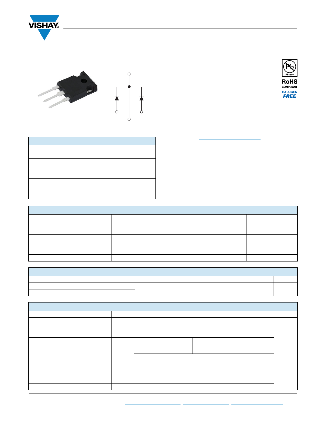
High Performance Schottky Rectifier, 2 x 15 A
Base
common
cathode
2
1
2
3
TO-247AC 3L
1
3
Anode
2 Anode
Common
cathode
PRIMARY CHARACTERISTICS
IF(AV)
VR
VF at IF
IRM max.
TJ max.
EAS
Package
2 x 15 A
35 V, 45 V
See Electrical table
100 mA at 125 °C
150 °C
10 mJ
TO-247AC 3L
Circuit configuration
Common cathode
FEATURES
• 150 °C TJ operation
• Very low forward voltage drop
• High frequency operation
• High purity, high temperature epoxy
encapsulation for enhanced mechanical
strength and moisture resistance
• Guard ring for enhanced ruggedness and long term
reliability
• Designed and qualified according to JEDEC®-JESD 47
• Material categorization: for definitions of compliance
please see www.vishay.com/doc?99912
DESCRIPTION
The VS-MBR30..WT... center tap Schottky rectifier has been
optimized for very low forward voltage drop, with moderate
leakage. The proprietary barrier technology allows for
reliable operation up to 150 °C junction temperature. Typical
applications are in switching power supplies, converters,
freewheeling diodes, and reverse battery protection.
MAJOR RATINGS AND CHARACTERISTICS
SYMBOL
CHARACTERISTICS
IF(AV)
IFRM
VRRM
IFSM
VF
TJ
Rectangular waveform (per device)
TC = 125 °C (per leg)
tp = 5 μs sine
20 Apk, TJ = 125 °C
Range
VALUES
30
30
35/45
1020
6
-65 to +150
UNITS
A
V
A
V
°C
VOLTAGE RATINGS
PARAMETER
Maximum DC reverse voltage
Maximum working peak reverse voltage
SYMBOL
VR
VRWM
VS-MBR3035WT-N3
35
VS-MBR3045WT-N3
45
UNITS
V
ABSOLUTE MAXIMUM RATINGS
PARAMETER
SYMBOL
Maximum average
forward current
per leg
per device
IF(AV)
Peak repetitive forward current per leg
IFRM
Non-repetitive peak surge current
IFSM
Non-repetitive avalanche energy per leg
Repetitive avalanche current per leg
Peak repetitive reverse surge current
EAS
IAR
IRRM
TEST CONDITIONS
TC = 125 °C, rated VR
Rated VR, square wave, 20 kHz TC = 125 °C
Following any rated load
5 μs sine or 3 μs rect. pulse condition and with rated
VRRM applied
Surge applied at rated load conditions half wave,
single phase, 60 Hz
TJ = 25 °C, IAS = 2 A, L = 5 mH
Current decaying linearly to zero in 1 μs
Frequency limited by TJ maximum VA = 1.5 x VR typical
2.0 μs 1.0 kHz
VALUES
15
30
30
1020
200
10
2
2.0
UNITS
A
mJ
A
Revision: 09-Apr-18
1
Document Number: 96483
For technical questions within your region: DiodesAmericas@vishay.com, DiodesAsia@vishay.com, DiodesEurope@vishay.com
THIS DOCUMENT IS SUBJECT TO CHANGE WITHOUT NOTICE. THE PRODUCTS DESCRIBED HEREIN AND THIS DOCUMENT
ARE SUBJECT TO SPECIFIC DISCLAIMERS, SET FORTH AT www.vishay.com/doc?91000
Share Link: 