MB90F483C Ver la hoja de datos (PDF) - Fujitsu
Número de pieza
componentes Descripción
Fabricante
MB90F483C Datasheet PDF : 124 Pages
| |||
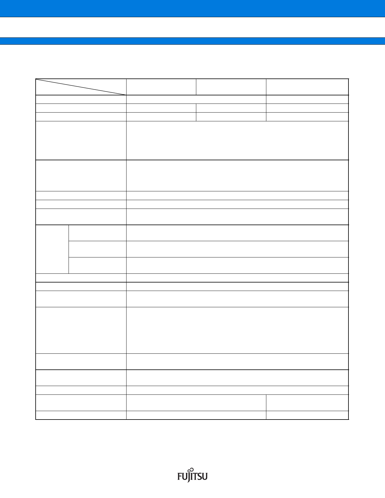
MB90480B/485B Series
■ PRODUCT LINEUP
MB90480B series
Item
Part number
Classification
ROM size
RAM size
CPU function
Ports
UART
8/16-bit PPG
8/16-bit up/down
counter/timer
16-bit
free-run timer
16-bit
Output compare
I/O timers (OCU)
Input capture
(ICU)
DTP/external interrupt circuit
Extended I/O serial interface
Timebase timer
A/D converter
Watchdog timer
Low-power consumption
(standby) modes
Process
Type
Emulator power supply*2
MB90F481B
MB90F482B
MB90V480B
Flash memory product
Evaluation product
192 Kbytes
256 Kbytes
4 Kbytes
6 Kbytes
16 Kbytes
Number of instructions : 351
Instruction bit length : 8-bit, 16-bit
Instruction length
: 1 byte to 7 bytes
Data bit length
: 1-bit, 8-bit, 16-bit
Minimum instruction execution time : 40 ns (25 MHz machine clock)
General-purpose I/O ports: up to 84
General-purpose I/O ports (CMOS output)
General-purpose I/O ports (with pull-up resistance)
General-purpose I/O ports (N-ch open drain output)
1 channel, start-stop synchronized
8-bit 6 channels/16-bit 3 channels
Event input pins : 6, 8-bit up/down counters : 2
8-bit reload/compare registers : 2
Number of channels : 1
Overflow interrupt
Number of channels : 6
Pin input factor : A match signal of compare register
Number of channels : 2
Rewriting a register value upon a pin input (rising, falling, or both edges)
Number of external interrupt pin channels : 8 (edge or level detection)
Embedded 2 channels
18-bit counter
Interrupt cycles: 1.0 ms, 4.1 ms, 16.4 ms, 131.1 ms (at 4 MHz base oscillator)
Conversion resolution : 8/10-bit, switchable
One-shot conversion mode (converts selected channel 1 time only)
Scan conversion mode (conversion of multiple consecutive channels,
programmable up to 8 channels)
Continuous conversion mode (repeated conversion of selected channels)
Stop conversion mode (conversion of selected channels with repeated pause)
Reset generation interval : 3.58 ms, 14.33 ms, 57.23 ms, 458.75 ms
(minimum value, at 4 MHz base oscillator)
Stop mode, sleep mode, CPU intermittent operation mode, watch mode,
timebase timer mode
CMOS
Not included security function
User pin*1,
3 V/5 V versions
Included
*1 : User pin : P20 to P27, P30 to P37, P40 to P47, P70 to P77
*2 : It is setting of Jumper switch (TOOL VCC) when emulator (MB2147-01) is used.
Please refer to the MB2147-01 or MB2147-20 hardware manual (3.3 Emulator-dedicated Power Supply
switching) about details.
Note : Ensure that you must write to Flash at VCC 3.13 V to 3.60 V (3.3 V 10 , 5 ) .
DS07-13722-11E
3
Share Link: 