MAX8790A Ver la hoja de datos (PDF) - Maxim Integrated
Número de pieza
componentes Descripción
Fabricante
MAX8790A
Maxim Integrated

MAX8790A Datasheet PDF : 22 Pages
| |||
MAX8790A
Six-String White LED Driver with Active
Current Balancing for LCD Panel Applications
Typical Operating Characteristics (continued)
(Circuit configuration 1, VIN = 12V, VSHDN = VIN, LEDs = 8 series x 6 parallel strings, ISET = VCC, TA = +25°C, unless otherwise noted.)
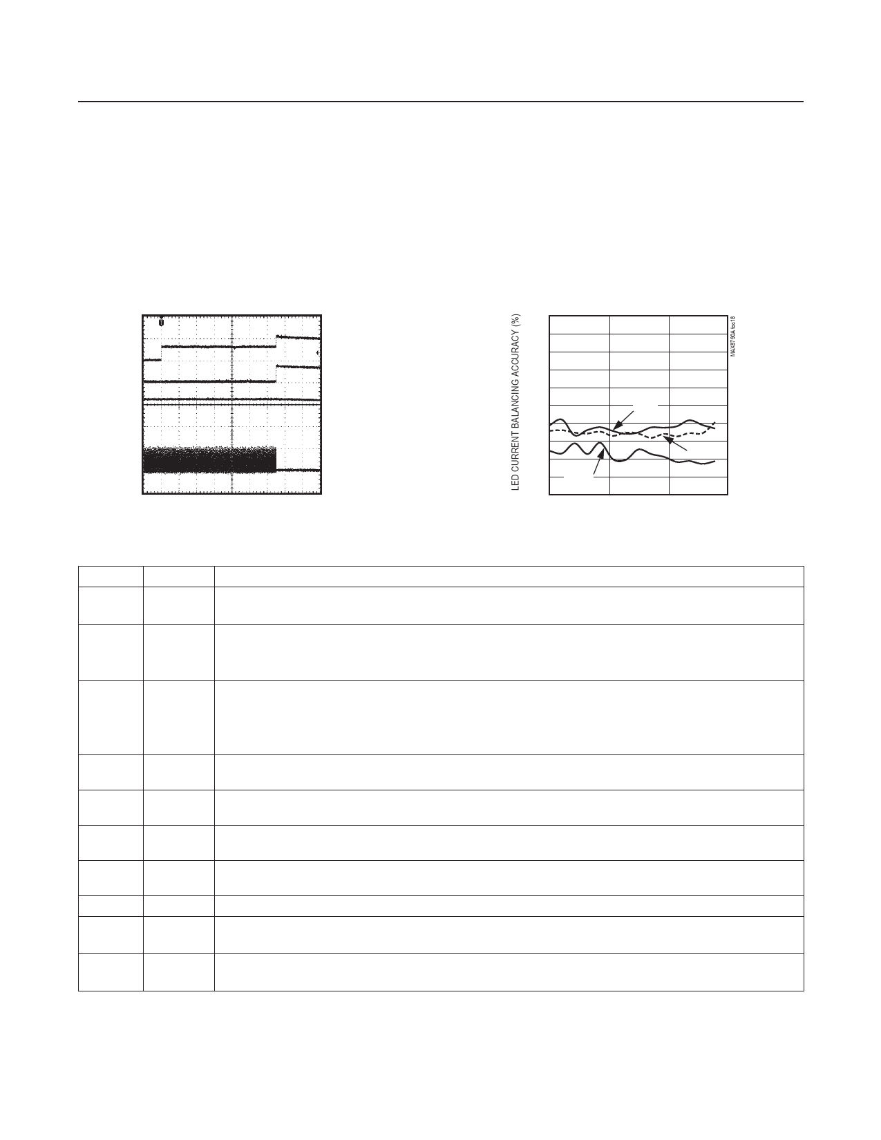
LED-SHORT FAULT PROTECTION
(BRT = 100%, 2 LEDs SHORT ON FB3)
MAX8790A toc17
0V
VFB3
1V/div
VFB1
0V 10V/div
VOUT
0V 20V/div
IL
0A 1A/div
10ms/div
LED CURRENT BALANCING
vs. INPUT VOLTAGE (BRT = 100%)
1.00
0.90
0.80
0.70
0.60
0.50
1MHz
0.40
0.30
0.20
0.10 750kHz
500kHz
0
7
12
17
INPUT VOLTAGE (V)
Pin Description
PIN
NAME
FUNCTION
1
OSC
Oscillator Frequency Selection Pin. Connect OSC to VCC to set the step-up converter’s oscillator frequency to
1MHz. Connect OSC to GND to set the frequency to 500kHz. Float OSC to set the frequency to 750kHz.
Analog Dimming Enable. ENA sets the PWM control mode. Set ENA LOW to enable direct DPWM dimming.
2
ENA Set ENA HIGH to enable analog dimming. In both modes, the duty cycle of the PWM signal at the BRT input
controls the LED current characteristics. See the Dimming Control section for a complete description.
Brightness Control Input. The duty cycle of this digital input signal controls the LED current characteristics.
3
BRT
The allowable frequency range is 100Hz to 500Hz in analog dimming mode. The duty cycle can be 100%
to 1%. The BRT frequency can go above 500Hz in direct DPWM mode as long as the BRT pulse width is
greater than 50µs minimum. See the Dimming Control section for a complete description.
4
SHDN
Shutdown Control Input. The MAX8790A shuts down when SHDN is less than 0.8V. Pulling SHDN above
2.1V enables the MAX8790A. SHDN can be connected to the input voltage if desired.
5
FB1
LED String 1 Cathode Connection. FB1 is the open-drain output of an internal regulator, which controls
current through FB1. FB1 can sink up to 27mA. If unused, connect FB1 to GND.
6
FB2
LED String 2 Cathode Connection. FB2 is the open-drain output of an internal regulator, which controls
current through FB2. FB2 can sink up to 27mA. If unused, connect FB2 to GND.
7
FB3
LED String 3 Cathode Connection. FB3 is the open-drain output of an internal regulator, which controls
current through FB3. FB3 can sink up to 27mA. If unused, connect FB3 to GND.
8
GND Ground
9
FB4
LED String 4 Cathode Connection. FB4 is the open-drain output of an internal regulator, which controls
current through FB4. FB4 can sink up to 27mA. If unused, connect FB4 to GND.
10
FB5
LED String 5 Cathode Connection. FB5 is the open-drain output of an internal regulator, which controls
current through FB5. FB5 can sink up to 27mA. If unused, connect FB5 to GND.
www.maximintegrated.com
Maxim Integrated │ 8
Share Link: