MAX6323UT-T Ver la hoja de datos (PDF) - Maxim Integrated
Número de pieza
componentes Descripción
Fabricante
MAX6323UT-T
Maxim Integrated

MAX6323UT-T Datasheet PDF : 14 Pages
| |||
MAX6323/MAX6324
μP Supervisory Circuits with Windowed
(Min/Max) Watchdog and Manual Reset
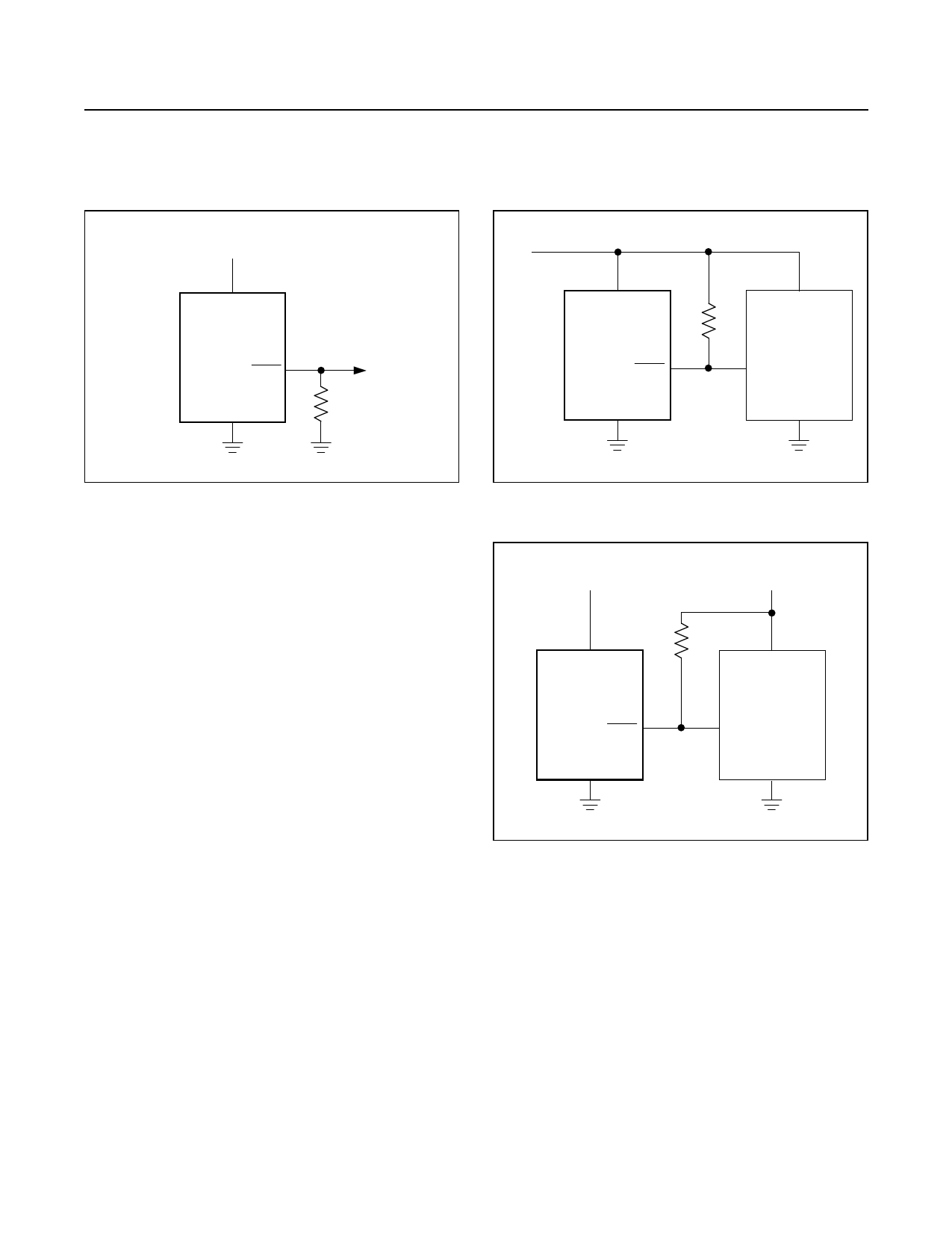
VCC
VCC
MAX6323
RESET
R1
GND
100k
VCC
VCC
MAX6324
RESET
GND
VCC
µP
RESET
INPUT
GND
Figure 6. RESET Valid to VCC = Ground Circuit
Figure 7. Interfacing to μPs with Bidirectional Reset Pins
Interfacing to μPs with
Bidirectional Reset Pins
Since the RESET output on the MAX6324 is open-
drain, this device easily interfaces with μPs that have
bidirectional reset pins, such as the Motorola 68HC11.
Connecting the μP supervisor’s RESET output directly
to the microcontroller’s (μC’s) RESET pin with a single
pullup resistor allows either device to assert reset
(Figure 7).
MAX6324 Open-Drain RESET Output
Allows Use with Multiple Supplies
Generally, the pullup resistor connected to the MAX6324
will connect to the supply voltage that is being monitored
at the IC’s VCC pin. However, some systems may use
the open-drain output to level-shift from the monitored
supply to reset circuitry powered by some other supply
(Figure 8). Keep in mind that as the MAX6324’s VCC
decreases below +1.2V, so does the IC’s ability to sink
current at RESET. Also, with any pullup resistor, RESET
will be pulled high as VCC decays toward 0. The voltage
where this occurs depends on the pullup resistor value
and the voltage to which it is connected.
Watchdog Software Considerations
To help the watchdog timer monitor software execution
more closely, set and reset the watchdog input at different
points in the program, rather than “pulsing” the watchdog
input high-low-high or low-high-low. This technique avoids
a “stuck” loop in which the watchdog time would continue
+3.3V
VCC
MAX6324
RESET
GND
+5.0V
RPULLUP
VCC
5V SYSTEM
RESET
INPUT
GND
Figure 8. MAX6324 Open-Drain RESET Output Allows Use
with Multiple Supplies
to be reset within the loop, keeping the watchdog from
timing out.
Figure 9 shows an example of a flow diagram where the
I/O driving the watchdog input is set high at the beginning
of the program, set low at the beginning of every subrou-
tine or loop, then set high again when the program returns
to the beginning. If the program should “hang” in any sub-
routine, the problem would be quickly corrected, since the
I/O is continually set low and the watchdog time is allowed
to time out, causing a reset or interrupt to be issued.
www.maximintegrated.com
Maxim Integrated │ 10
Share Link: