MAX399C/D Ver la hoja de datos (PDF) - Maxim Integrated
Número de pieza
componentes Descripción
Fabricante
MAX399C/D Datasheet PDF : 12 Pages
| |||
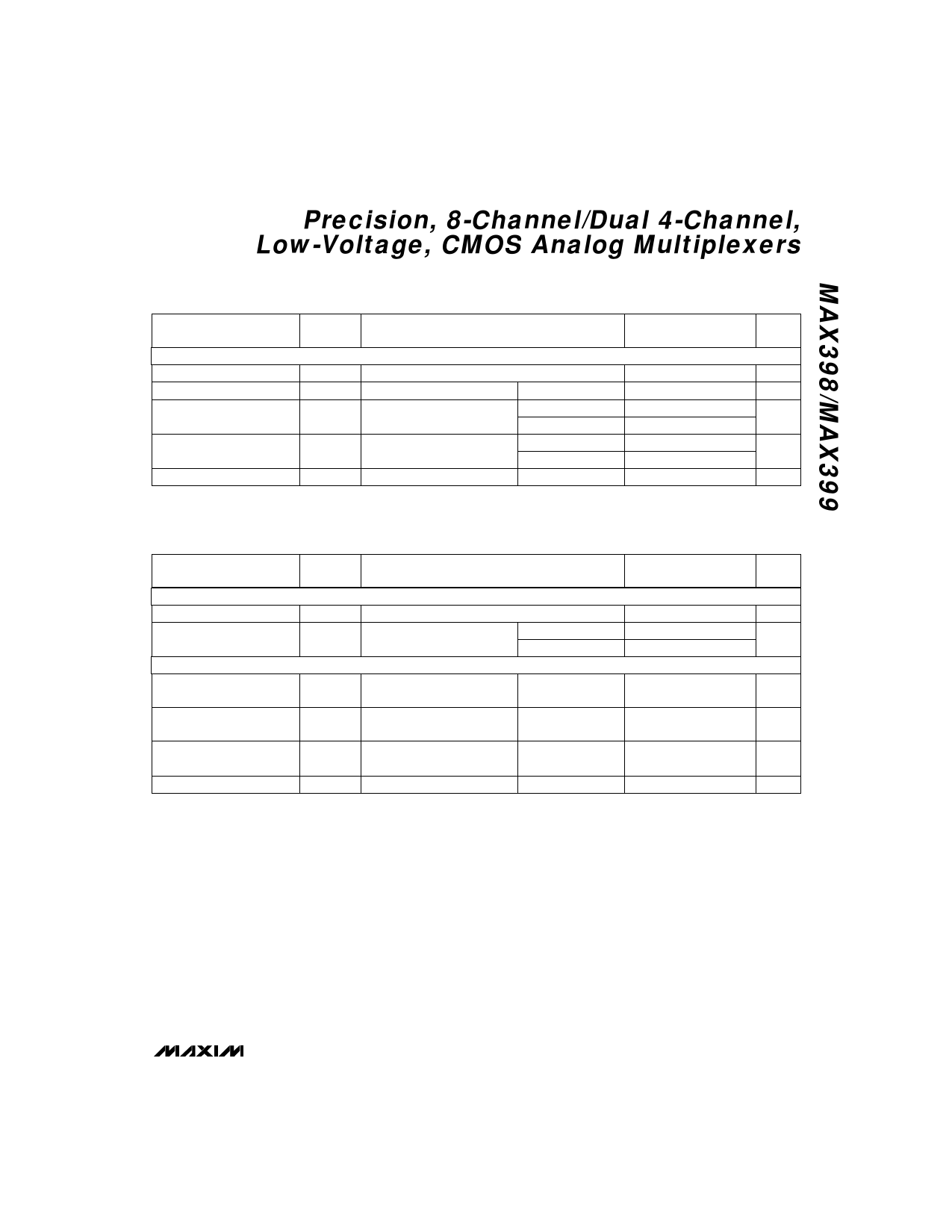
Precision, 8-Channel/Dual 4-Channel,
Low-Voltage, CMOS Analog Multiplexers
ELECTRICAL CHARACTERISTICS—Single 5V (continued)
(V+ = 5V ±10%, V- = 0V, GND = 0V, VAH = VENH = +2.4V, VAL = VENL = +0.8V, TA = TMIN to TMAX, unless otherwise noted.)
PARAMETER
SYMBOL
CONDITIONS
MIN TYP MAX
(Note 2)
UNITS
DYNAMIC
Transition Time
tTRANS VNO = 3V
90 245
ns
Break-Before-Make Interval tOPEN
TA = +25°C
10
40
ns
Enable Turn-On Time
tON(EN)
TA = +25°C
TA = TMIN to TMAX
90 200
ns
275
Enable Turn-Off Time
Charge Injection (Note 3)
tOFF(EN)
Q
CL = 10nF, VS = 0V, RS = 0Ω
TA = +25°C
TA = TMIN to TMAX
TA = +25°C
50 125
ns
200
1.5
5
pC
ELECTRICAL CHARACTERISTICS—Single 3V
(V+ = 3V ±10%, V- = 0V, GND = 0V, VAH = VENH = +2.4V, VAL = VENL = +0.8V, TA = TMIN to TMAX, unless otherwise noted.)
PARAMETER
SYMBOL
CONDITIONS
SWITCH
Analog Signal Range
On-Resistance
DYNAMIC
Transition Time (Note 3)
VANALOG
RON
tTRANS
Enable Turn-On Time (Note 3) tON(EN)
Enable Turn-Off Time (Note 3) tOFF(EN)
Charge Injection (Note 3)
Q
(Note 3)
INO = 1mA, VCOM = 1.5V,
V+ = 3V
Figure 1, VIN = 2.4V,
VN01 = 1.5V, VN08 = 0V
Figure 3, VINH = 2.4V,
VINL = 0V, VN01 = 1.5V
Figure 3, VINH = 2.4V,
VINL = 0V, VN01 = 1.5V
CL = 10nF, VS = 0V, RS = 0Ω
TA = +25°C
TA = TMIN to TMAX
TA = +25°C
TA = +25°C
TA = +25°C
TA = +25°C
MIN TYP MAX
(Note 2)
UNITS
V-
V+
V
230 375
Ω
425
230 575
ns
200 500
ns
75 400
ns
1
5
pC
Note 2: The algebraic convention, where the most negative value is a minimum and the most positive value a maximum, is used in
this data sheet.
Note 3: Guaranteed by design.
Note 4: ∆RON = RONMAX - RONMIN.
Note 5: Flatness is defined as the difference between the maximum and minimum value of on-resistance as measured over the
specified analog signal ranges, i.e., VNO = 3V to 0V and 0V to -3V.
Note 6: Leakage parameters are 100% tested at maximum rated hot operating temperature, and guaranteed by correlation at +25°C.
Note 7: Worst-case isolation is on channel 4 because of its proximity to the COM pin. Off isolation = 20log VCOM/VNO, VCOM = output,
VNO = input to off switch.
Note 8: Leakage testing at single supply is guaranteed by correlation testing with dual supplies.
_______________________________________________________________________________________ 5
Share Link: 