MAX2116(2005) Ver la hoja de datos (PDF) - Maxim Integrated
Número de pieza
componentes Descripción
Fabricante
MAX2116 Datasheet PDF : 15 Pages
| |||
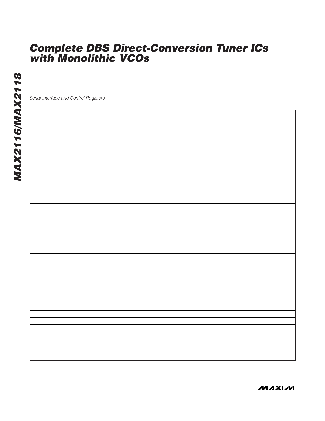
Complete DBS Direct-Conversion Tuner ICs
with Monolithic VCOs
AC ELECTRICAL CHARACTERISTICS (continued)
(MAX2116/MAX2118 EV kits, VCC = +4.75V to +5.25V, GC1 and GC2 set for maximum gain, GND = 0V, IOUT = QOUT = 800mVP-P
(MAX2116), loaded with 1kΩ IOUT± = QOUT± = 590mVP-P differential (DL = 0, MAX2118), IOUT± = QOUT± = 1VP-P differential (DL
= 1, MAX2118), loaded with differential 2kΩ. Baseband LPF BW = 33MHz, fRFIN = 2175MHz. For default register values, see the
Serial Interface and Control Registers section. TA = +25°C to +85°C. Typical values are at VCC = +5V, TA = +25°C, unless otherwise
noted.) (Note 1)
PARAMETER
Input Carrier Levels Necessary to Produce
1VP-P (Differential) at I/Q Baseband Outputs
(MAX2118)
Input Carrier Levels Necessary to Produce
590mVP-P (Differential) at I/Q Baseband
Outputs (MAX2118)
RF Gain Control (GC1) Range
Baseband Gain Control (GC2) Range
IIP3
IIP2
NF
Minimum RF Input Return Loss
Maximum LO Leakage at RFIN
LO-Generated RFIN Second Harmonic
Rejection
BASEBAND OUTPUTS
Baseband I/Q Output Impedance
Baseband Highpass -3dB Point
Quadrature Phase Error
Quadrature Gain Error
Baseband Lowpass BW Range
LP Filter BW Accuracy
Ratio of In-Filter-Band to Out-of-Filter-Band
Noise
CONDITIONS
GC1 = 0.75V (max gain), bit DL = 1,
bits GC2(4) - GC2(0) = 00000 (max gain)
for output ≥ 800mVP-P
GC1 = 2.6V (min gain), bit DL = 1,
bits GC2(4) - GC2(0) = 11111 (min gain),
for output ≤ 800mVP-P
GC1 = 0.75V (max gain), bit DL = 0,
bits GC2(4) - GC2(0) = 00000 (max gain),
for output ≥ 800mVP-P
GC1 = 2.6V (min gain), bit DL = 0,
bits GC2(4) - GC2(0) = 11111 (min gain),
for output ≤ 800 mVP-P
0.75V < GC1 < 2.6V
Bits GC2(4) - GC2(0) = 00000 to 11111
(Note 5)
(Note 6)
GC1 = 0.75V (max gain), bits GC2(4) - GC2(0)
= 00000 (max gain)
75Ω input source, 925MHz < fRFIN < 2175MHz
925MHz < fLO < 2175MHz
Unwanted in 925MHz to 2175MHz band
Unwanted = 2250MHz
Unwanted above 2250MHz
MIN TYP MAX
-77
-72
3
16
-77
-72
3
16
60
69
19
24
10
22
10.5
13.5
-80
-63
33
50
30
45
6dB/oct
UNITS
dBm
dBm
dB
dB
dBm
dBm
dB
dB
dBm
dB
Single ended, real ZOUT
0.1µF capacitors at IDC±, QDC±
125kHz baseband test tone
125kHz baseband test tone
Baseband -3dB cutoff frequency
Fc = 4MHz
Fc = 33MHz (Note 7)
Finband = 100Hz to 22.5MHz,
Foutband = 87.5MHz to 112.5MHz
30
Ω
850
Hz
4 Degrees
1.2
dB
4
33
MHz
-5.5
+5.5
%
-10
+10
%
25
dB
4 _______________________________________________________________________________________
Share Link: 