LZ0P3612 Ver la hoja de datos (PDF) - Sharp Electronics
Número de pieza
componentes Descripción
Fabricante
LZ0P3612 Datasheet PDF : 14 Pages
| |||
LZ0P3610/3611/3612/3615
∫Under development
CHARACTERISTICS FOR LZ0P3612∫ (Drive method : Field accumulation)
(TA : +25 ˚C, Operating conditions : The typical values specified in "RECOMMENDED OPERATING CONDITIONS".
Color temperature of light source : 3 200 K)
PARAMETER
SYMBOL
MIN.
TYP.
MAX.
UNIT
NOTE
Standard output voltage
Saturation output voltage
VO
VSAT
150
700
mV
1
mV
2
Sensitivity
R
400
500
mV
3
Resolution (at center)
250
300
TV line
4
Resolution (at corner)
150
200
TV line
5
Shading
50
%
6
Difference of center position
±10
%
7
Output transistor drain current
IOD
4.0
8.0
mA
NOTES :
1. The average output voltage in the central area (H/10,
can be distinguished on the B/W video monitor.
V/10) under uniform illumination.
5. The resolution in the peripheral area (image height : Y =
The standard exposure conditions are defined as when
0.8) under the conditions mentioned above.
VO is 150 mV.
6. Defined by the following formula at the brightness of
2. The average output voltage in the central area (H/10,
standard output voltage : (Vco/Vce) x 100 [%]
V/10) under 10 times exposure of the standard exposure
Vco : Output voltage at edge of the image (at video output).
conditions.
Vce : Output voltage at center of the image (at video output).
3. The average output voltage in the central area (H/10,
7. The difference between the center position of image and
V/10) when a 1 000 lux light source with a white board
that of the monitor. This is the ratio for the horizontal
of 90% reflector is imaged.
underscanning monitor size which includes the decentering
4. The resolution in the central area (H/10, V/10) at which
eccentricity when turning the lens head one time.
the image of the TV resolution chart (ex. EIAJ test chart)
LENS SPECIFICATION FOR LZ0P3612∫
PARAMETER
Construction
Focal length
F No.
Viewing angle
TV distortion
Focus adjustment range
Torque of focusing
SPECIFICATION
2 pcs. (non-spherical, plastic)
3.0 mm [TYP. : reference]
2.8±5%
H : 62˚, V : 49˚, Diagonal : 74˚ [TYP. : reference]
≤ –1.0%
∞ to 10 cm
0.00005 to 0.001 N·m
NOTE
1
2
3
NOTES :
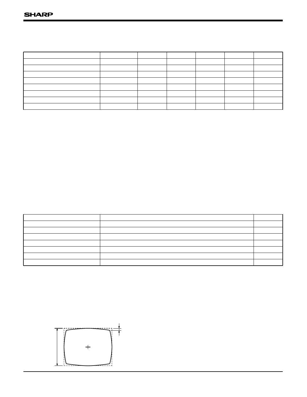
1. TV distortion is defined by the formula, (∆y/y) x 100 [%]
2. The best focus point of an object can be obtained by
at capturing rectangular pattern sized horizontal by
turning the lens head within this range.
vertical as 4 by 3.
3. Torques which are necessary for turning the lens.
"y" is defined as the vertical height of the center of the
horizontal line.
* Be careful not to remove the lens head by turning it
∆y is defined as the difference between the vertical height
counterclockwise too much when adjusting macro.
of the center of the horizontal line and an edge of it.
∆y
y
6
Share Link: 