MAC15S Ver la hoja de datos (PDF) - ON Semiconductor
Número de pieza
componentes Descripción
Fabricante
MAC15S Datasheet PDF : 7 Pages
| |||
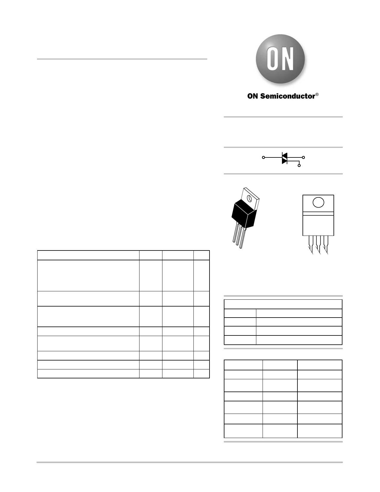
MAC15SD, MAC15SM,
MAC15SN
Preferred Device
Sensitive Gate Triacs
Silicon Bidirectional Thyristors
Designed for industrial and consumer applications for full wave
control of AC loads such as appliance controls, heater controls, motor
controls, and other power switching applications.
Features
• Sensitive Gate allows Triggering by Microcontrollers and other
Logic Circuits
• High Immunity to dv/dt − 25 V/ms minimum at 110°C
• High Commutating di/dt − 8.0 A/ms minimum at 110°C
• Maximum Values of IGT, VGT and IH Specified for Ease of Design
• On-State Current Rating of 15 Amperes RMS at 70°C
• High Surge Current Capability − 120 Amperes
• Blocking Voltage to 800 Volts
• Rugged, Economical TO−220AB Package
• Uniform Gate Trigger Currents in Three Quadrants, Q1, Q2, and Q3
• Pb−Free Packages are Available*
MAXIMUM RATINGS (TJ = 25°C unless otherwise noted)
Rating
Symbol Value Unit
Peak Repetitive Off−State Voltage (Note 1) VDRM,
V
(TJ = −40 to 110°C, Sine Wave, 50 to
VRRM
60 Hz, Gate Open)
MAC15SD
400
MAC15SM
600
MAC15SN
800
On−State RMS Current
IT(RMS)
15
A
(Full Cycle Sine Wave, 60Hz, TJ = 70°C)
Peak Non-repetitive Surge Current
(One Full Cycle Sine Wave, 60 Hz,
TJ = 110°C)
Circuit Fusing Consideration (t = 8.3 ms)
ITSM
I2t
120
A
60
A2s
Peak Gate Power
(Pulse Width ≤ 1.0 ms, TC = 70°C)
PGM
20
W
Average Gate Power (t = 8.3 ms, TC = 70°C) PG(AV)
0.5
W
Operating Junction Temperature Range
TJ
−40 to +110 °C
Storage Temperature Range
Tstg −40 to +150 °C
Maximum ratings are those values beyond which device damage can occur.
Maximum ratings applied to the device are individual stress limit values (not
normal operating conditions) and are not valid simultaneously. If these limits are
exceeded, device functional operation is not implied, damage may occur and
reliability may be affected.
1. VDRM and VRRM for all types can be applied on a continuous basis. Blocking
voltages shall not be tested with a constant current source such that the
voltage ratings of the devices are exceeded.
*For additional information on our Pb−Free strategy and soldering details, please
download the ON Semiconductor Soldering and Mounting Techniques
Reference Manual, SOLDERRM/D.
http://onsemi.com
TRIACS
15 AMPERES RMS
400 thru 800 VOLTS
MT2
MT1
G
MARKING
DIAGRAM
123
TO−220AB
CASE 221A−09
STYLE 4
MAC15SxG
AYWW
x = D, M, or N
A = Assembly Location
Y = Year
WW = Work Week
G = Pb−Free Package
PIN ASSIGNMENT
1
Main Terminal 1
2
Main Terminal 2
3
Gate
4
Main Terminal 2
ORDERING INFORMATION
Device
Package
Shipping
MAC15SD
TO−220AB
50 Units / Rail
MAC15SDG
MAC15SM
TO−220AB
(Pb−Free)
TO−220AB
50 Units / Rail
50 Units / Rail
MAC15SMG
MAC15SN
TO−220AB
(Pb−Free)
TO−220AB
50 Units / Rail
50 Units / Rail
MAC15SNG
TO−220AB
(Pb−Free)
50 Units / Rail
Preferred devices are recommended choices for future use
and best overall value.
© Semiconductor Components Industries, LLC, 2005
1
December, 2005 − Rev. 5
Publication Order Number:
MAC15S/D
Share Link: 