MAC4DCN Ver la hoja de datos (PDF) - Motorola => Freescale
Número de pieza
componentes Descripción
Fabricante
MAC4DCN Datasheet PDF : 8 Pages
| |||
MOTOROLA
SEMICONDUCTOR TECHNICAL DATA
Order this document
by MAC4DCM/D
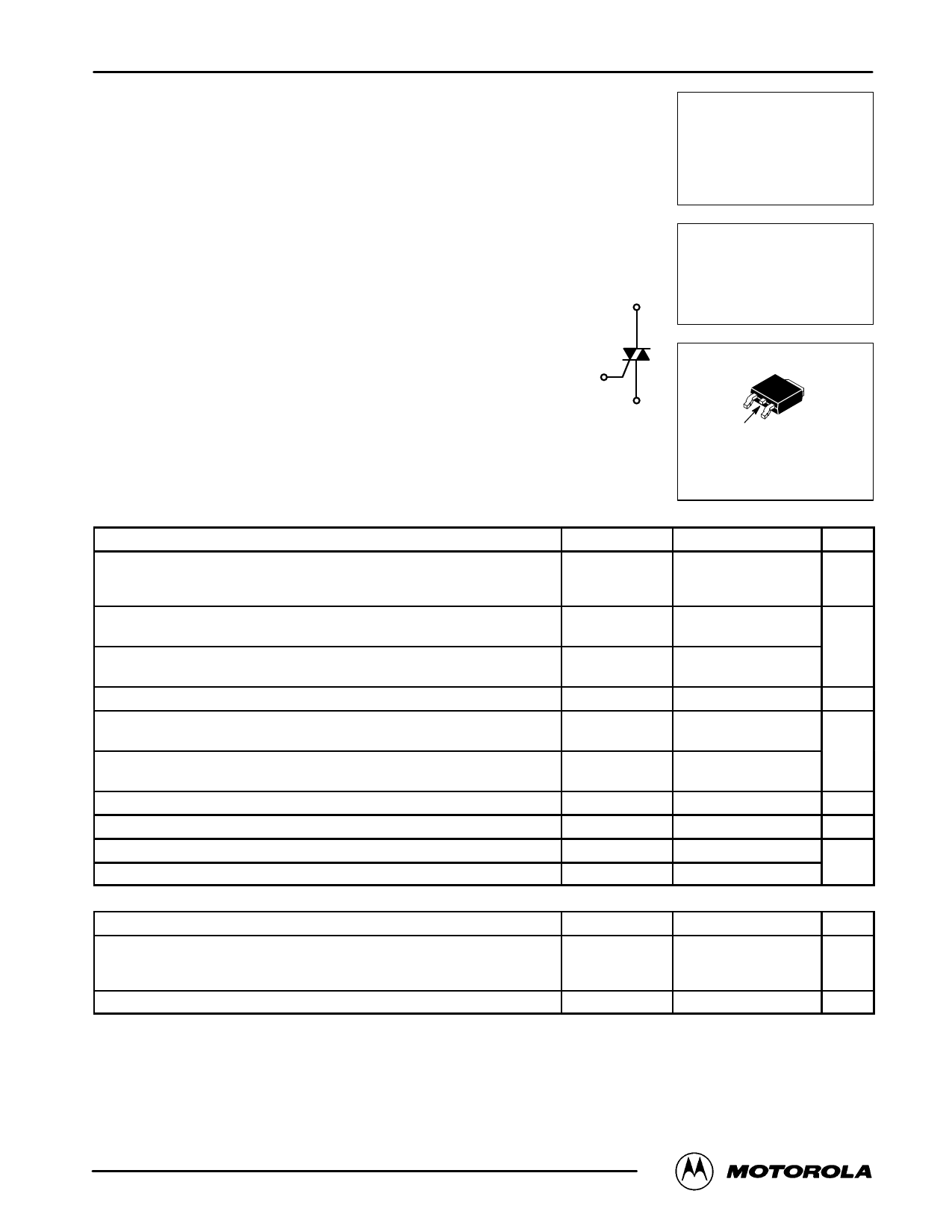
TRIACS
Silicon Bidirectional Thyristors
Designed for high volume, low cost, industrial and consumer applications
such as motor control; process control; temperature, light and speed control.
• Small Size Surface Mount DPAK Package
• Passivated Die for Reliability and Uniformity
• Blocking Voltage to 800 V
MT2
• On–State Current Rating of 4.0 Amperes RMS at 108°C
• High Immunity to dv/dt — 500 V/ms at 125°C
• High Immunity to di/dt — 6.0 A/ms at 125°C
ORDERING INFORMATION
G
• To Obtain “DPAK” in Surface Mount Leadform (Case 369A)
Shipped in Sleeves — No Suffix, i.e. MAC4DCN
MT1
Shipped in 16 mm Tape and Reel — Add “T4” Suffix to Device Number,
i.e. MAC4DCNT4
• To Obtain “DPAK” in Straight Lead Version (Case 369) Shipped in Sleeves —
Add “–1” Suffix to Device Number, i.e. MAC4DCN–1
MAC4DCM
MAC4DCN
Motorola Preferred Devices
TRIACS
4.0 AMPERES RMS
600 thru 800 VOLTS
MT2
MT1
MT2 G
CASE 369A–13
STYLE 6
MAXIMUM RATINGS (TJ = 25°C unless otherwise noted)
Rating
Peak Repetitive Off–State Voltage (1)
(TJ = –40 to 125°C, Sine Wave, 50 to 60 Hz, Gate Open)
MAC4DCM
MAC4DCN
Symbol
VDRM
Value
600
800
Unit
Volts
On–State RMS Current
(Full Cycle Sine Wave, 60 Hz, TC = 108°C)
Peak Non–Repetitive Surge Current
(One Full Cycle, 60 Hz, TJ = 125°C)
Circuit Fusing Consideration (t = 8.3 msec)
IT(RMS)
ITSM
I2t
Amps
4.0
40
6.6
A2sec
Peak Gate Power
(Pulse Width ≤ 10 msec, TC = 108°C)
Average Gate Power
(t = 8.3 msec, TC = 108°C)
Peak Gate Current (Pulse Width ≤ 10 msec, TC = 108°C)
Peak Gate Voltage (Pulse Width ≤ 10 msec, TC = 108°C)
Operating Junction Temperature Range
Storage Temperature Range
THERMAL CHARACTERISTICS
PGM
PG(AV)
IGM
VGM
TJ
Tstg
0.5
0.1
0.5
5.0
–40 to 125
–40 to 150
Watts
Amps
Volts
°C
Characteristic
Symbol
Max
Unit
Thermal Resistance — Junction to Case
Thermal Resistance — Junction to Ambient
Thermal Resistance — Junction to Ambient (2)
RqJC
RqJA
RqJA
3.5
°C/W
88
80
Maximum Lead Temperature for Soldering Purposes (3)
TL
260
°C
(1) VDRM for all types can be applied on a continuous basis. Ratings apply for zero or negative gate voltage; positive gate voltage shall not be
applied concurrent with negative potential on the anode. Blocking voltages shall not be tested with a constant current source such that the
voltage ratings of the device are exceeded.
(2) Surface mounted on minimum recommended pad size.
(3) 1/8″ from case for 10 seconds.
Preferred devices are Motorola recommended choices for future use and best overall value.
Motorola Thyristor Device Data
1
© Motorola, Inc. 1997
Share Link: 