M95160-RMC6P(2014) Ver la hoja de datos (PDF) - STMicroelectronics
Número de pieza
componentes Descripción
Fabricante
M95160-RMC6P Datasheet PDF : 47 Pages
| |||
M95160 M95160-W M95160-R M95160-DF
4
Connecting to the SPI bus
Connecting to the SPI bus
All instructions, addresses and input data bytes are shifted in to the device, most significant
bit first. The Serial Data Input (D) is sampled on the first rising edge of the Serial Clock (C)
after Chip Select (S) goes low.
All output data bytes are shifted out of the device, most significant bit first. The Serial Data
Output (Q) is latched on the first falling edge of the Serial Clock (C) after the instruction
(such as the Read from Memory Array and Read Status Register instructions) have been
clocked into the device.
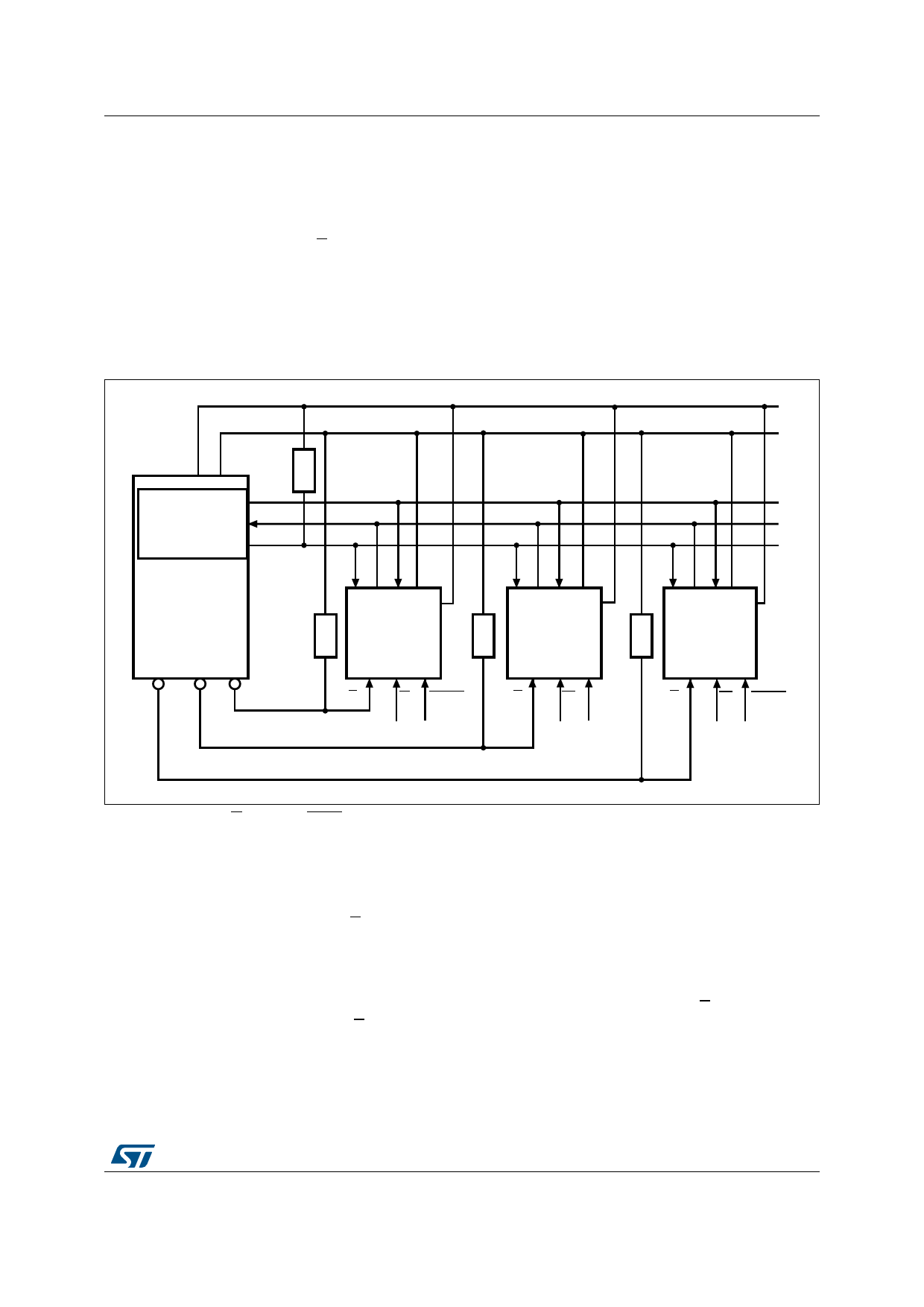
Figure 5. Bus master and memory devices on the SPI bus
2
30)�)NTERFACE�WITH
#0/,
�#0(! �
� �OR�
�
3$/
3$)
3#+
30)�"US�-ASTER
633
6##
#1$
6##
633
#1$
6##
633
# 1 $ 6##
633
#3 #3 #3
2
30)�-EMORY 2
$EVICE
3
7 (/,$
30)�-EMORY 2
$EVICE
30)�-EMORY
$EVICE
3
7 (/,$
3
7 (/,$
!)B
1. The Write Protect (W) and Hold (HOLD) signals should be driven, high or low as appropriate.
Figure 5 shows an example of three memory devices connected to an SPI bus master. Only
one memory device is selected at a time, so only one memory device drives the Serial Data
Output (Q) line at a time. The other memory devices are high impedance.
The pull-up resistor R (represented in Figure 5) ensures that a device is not selected if the
Bus Master leaves the S line in the high impedance state.
In applications where the Bus Master may leave all SPI bus lines in high impedance at the
same time (for example, if the Bus Master is reset during the transmission of an instruction),
the clock line (C) must be connected to an external pull-down resistor so that, if all
inputs/outputs become high impedance, the C line is pulled low (while the S line is pulled
high): this ensures that S and C do not become high at the same time, and so, that the
tSHCH requirement is met. The typical value of R is 100 kΩ.
DocID022580 Rev 5
11/47
46
Share Link: 