M59DR032EB Ver la hoja de datos (PDF) - STMicroelectronics
Número de pieza
componentes Descripción
Fabricante
M59DR032EB Datasheet PDF : 43 Pages
| |||
M59DR032EA, M59DR032EB
STATUS REGISTER
The Status Register provides information on the
current or previous Program or Erase operations.
Bus Read operations from any address within the
bank, always read the Status Register during Pro-
gram and Erase operations.
The various bits convey information about the sta-
tus and any errors of the operation.
The bits in the Status Register are summarized in
Table 12, Status Register Bits. Refer to Tables 11
and 12 in conjunction with the following text de-
scriptions.
Data Polling Bit (DQ7). When Program opera-
tions are in progress, the Data Polling bit outputs
the complement of the bit being programmed on
DQ7. For a Double Word Program operation, it is
the complement of DQ7 for the last Word written to
the Command Interface.
During an Erase operation, it outputs a ’0’. After
completion of the operation, DQ7 will output the bit
last programmed or a ’1’ after erasing.
Data Polling is valid and only effective during P/
E.C. operation, that is after the fourth W pulse for
programming or after the sixth W pulse for erase.
It must be performed at the address being pro-
grammed or at an address within the block being
erased. See Figure 21 for the Data Polling flow-
chart and Figure 12 for the Data Polling wave-
forms.
DQ7 will also flag an Erase Suspend by switching
from ’0’ to ’1’ at the start of the Erase Suspend. In
order to monitor DQ7 in the Erase Suspend mode
an address within a block being erased must be
provided. DQ7 will output ’1’ if the read is attempt-
ed on a block being erased and the data value on
other blocks. During a program operation in Erase
Suspend, DQ7 will have the same behavior as in
the normal program.
Toggle Bit (DQ6). When Program or Erase oper-
ations are in progress, successive attempts to
read DQ6 will output complementary data. DQ6
will toggle following the toggling of either G or E.
The operation is completed when two successive
reads give the same output data. The next read
will output the bit last programmed or a ’1’ after
erasing.
The Toggle Bit DQ6 is valid only during P/E.C. op-
erations, that is after the fourth W pulse for pro-
gramming or after the sixth W pulse for Erase.
DQ6 will be set to ’1’ if a read operation is attempt-
ed on an Erase Suspend block. When erase is
suspended DQ6 will toggle during programming
operations in a block different from the block in
Erase Suspend.
See Figure 15 for Toggle Bit flowchart and Figure
13 for Toggle Bit waveforms.
Toggle Bit (DQ2). Toggle Bit DQ2, together with
DQ6, can be used to determine the device status
during erase operations.
During Erase Suspend a read from a block being
erased will cause DQ2 to toggle. A read from a
block not being erased will output data. DQ2 will
be set to '1' during program operation and to ‘0’ in
erase operation. If a read operation is addressed
to a block where an erase error has occurred, DQ2
will toggle.
Error Bit (DQ5). The Error Bit can be used to
identify if an error occurs during a program or
erase operation.
The Error Bit is set to ‘1’ when a program or erase
operation has failed. When it is set to ‘0’ the pro-
gram or erase operation was successful.
If any Program command is used to try to set a bit
from ‘0’ to ‘1’ Status Register Error bit DQ5 will be
set to ‘1’, only if VPP is in the range of 11.4V to
12.6V.
The Error Bit is reset by a Read/Reset command.
Erase Timer Bit (DQ3). The Erase Timer bit is
used to indicate the timeout period for an erase
operation.
When the last block Erase command has been en-
tered to the Command Interface and it is waiting
for the erase operation to start, the Erase Timer Bit
is set to ‘0’. When the erase timeout period is fin-
ished, DQ3 returns to ‘1’, (80µs to 120µs).
DQ0, DQ1 and DQ4 are reserved for future use
and should be masked.
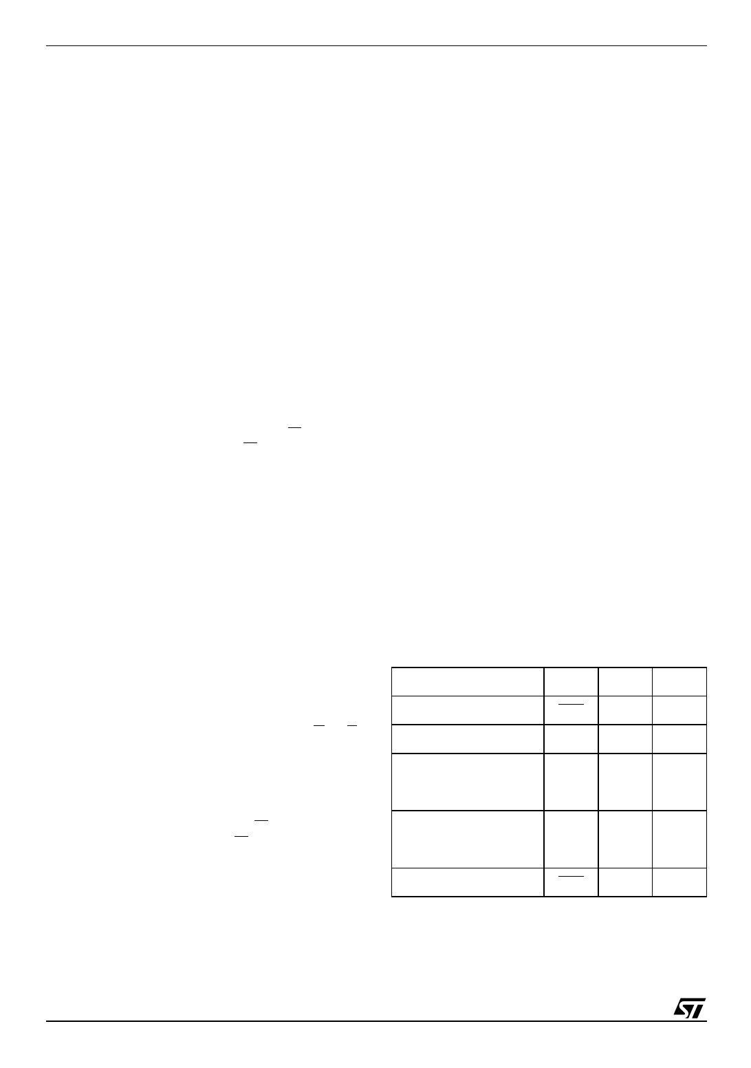
Table 11. Polling and Toggle Bits
Mode
DQ7 DQ6 DQ2
Program
DQ7 Toggle
1
Erase
0
Toggle N/A
Erase Suspend Read
(in Erase Suspend
block)
1
1
Toggle
Erase Suspend Read
(outside Erase Suspend
block)
DQ7
DQ6
DQ2
Erase Suspend Program DQ7 Toggle
1
18/43
Share Link: 