M34C02-RDS1 Ver la hoja de datos (PDF) - STMicroelectronics
NГәmero de pieza
componentes DescripciГіn
Fabricante
M34C02-RDS1 Datasheet PDF : 26 Pages
| |||
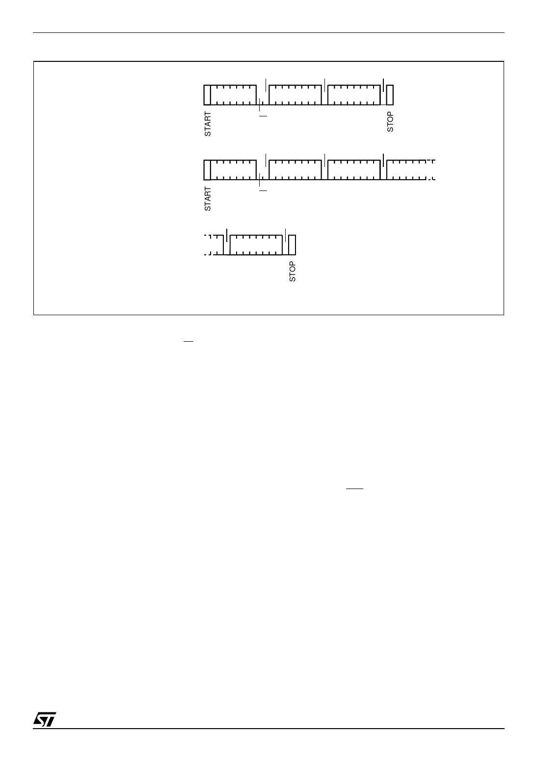
Figure 8. Write Mode Sequences in a Non Write-Protected Area
ACK
ACK
ACK
BYTE WRITE
DEV SEL
BYTE ADDR
DATA IN
R/W
PAGE WRITE
ACK
ACK
ACK
DEV SEL
BYTE ADDR DATA IN 1
DATA IN 2
R/W
ACK
ACK
DATA IN N
M34C02
Write Operations
Following a Start condition the bus master sends
a Device Select Code with the RW bit reset to 0.
The device acknowledges this, as shown in Figure
8, and waits for an address byte. The device re-
sponds to the address byte with an acknowledge
bit, and then waits for the data byte.
When the bus master generates a Stop condition
immediately after the Ack bit (in the вҖң10th bitвҖқ time
slot), either at the end of a Byte Write or a Page
Write, the internal memory Write cycle is triggered.
A Stop condition at any other time slot does not
trigger the internal Write cycle.
During the internal Write cycle, Serial Data (SDA)
and Serial Clock (SCL) are ignored, and the de-
vice does not respond to any requests.
Byte Write
After the Device Select Code and the address
byte, the bus master sends one data byte. If the
addressed location is hardware write-protected,
the device replies to the data byte with NoAck, and
the location is not modified. If, instead, the ad-
dressed location is not Write-protected, the device
AI01941
replies with Ack. The bus master terminates the
transfer by generating a Stop condition, as shown
in Figure 8.
Page Write
The Page Write mode allows up to 16 bytes to be
written in a single Write cycle, provided that they
are all located in the same page in the memory:
that is, the most significant memory address bits
are the same. If more bytes are sent than will fit up
to the end of the page, a condition known as вҖҳroll-
overвҖҷ occurs. This should be avoided, as data
starts to become overwritten in an implementation
dependent way.
The bus master sends from 1 to 16 bytes of data,
each of which is acknowledged by the device if
Write Control (WC) is Low. If the addressed loca-
tion is hardware write-protected, the device replies
to the data byte with NoAck, and the locations are
not modified. After each byte is transferred, the in-
ternal byte address counter (the 4 least significant
address bits only) is incremented. The transfer is
terminated by the bus master generating a Stop
condition.
7/26
Share Link: 