M34C02(1999) Ver la hoja de datos (PDF) - STMicroelectronics
NГәmero de pieza
componentes DescripciГіn
Fabricante
M34C02 Datasheet PDF : 19 Pages
| |||
M34C02
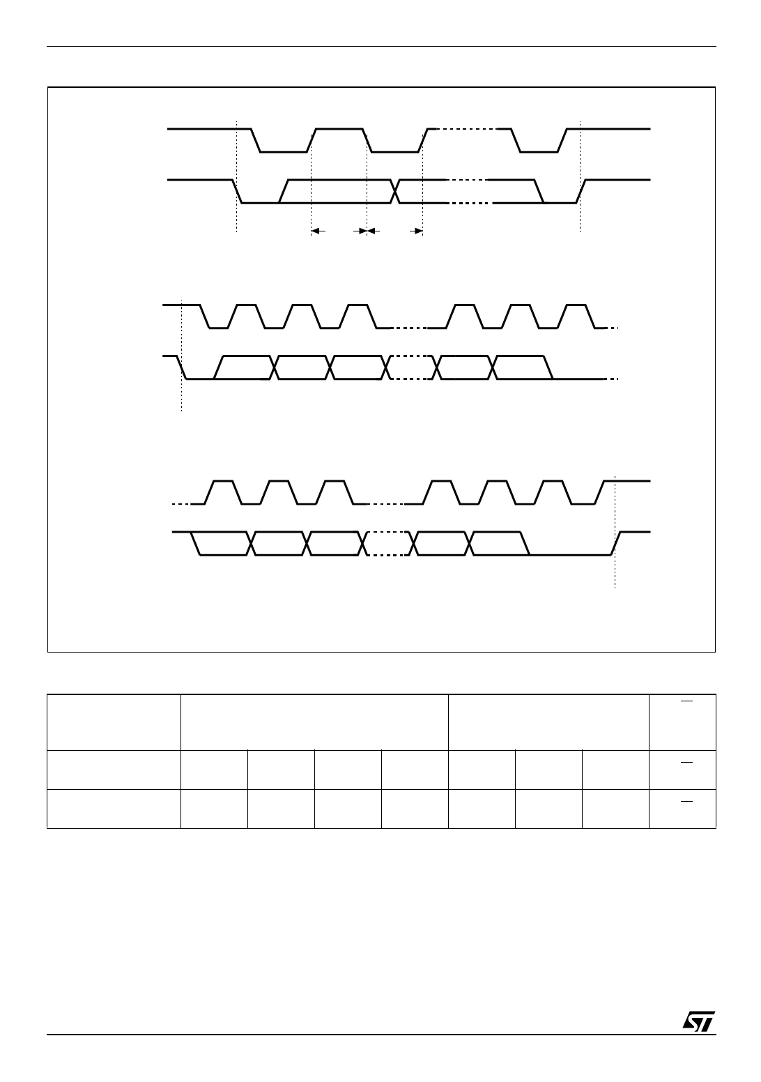
Figure 4. I2C Bus Protocol
SCL
SDA
START
CONDITION
SDA
SDA
INPUT CHANGE
STOP
CONDITION
SCL
SDA
1
2
3
MSB
START
CONDITION
7
8
9
ACK
SCL
1
2
3
7
8
9
SDA
MSB
ACK
STOP
CONDITION
AI00792
Start Condition
START is identified by a high to low transition of
the SDA line while the clock, SCL, is stable in the
high state. A START condition must precede any
data transfer command. The memory device
continuously monitors (except during a
programming cycle) the SDA and SCL lines for a
START condition, and will not respond unless one
is given.
Stop Condition
STOP is identified by a low to high transition of the
SDA line while the clock SCL is stable in the high
state. A STOP condition terminates
communication between the memory device and
the bus master. A STOP condition at the end of a
Read command, provided that it is followed by a
NoAck, forces the memory device into its standby
state. A STOP condition at the end of a Write
Table 3. Device Select Code 1
Device Type Identifier
Chip Enable
RW
b7
b6
b5
b4
b3
b2
b1
b0
Memory Area Select Code (two arrays)
1
0
1
0
E2
E1
E0
RW
Protection Register Select Code
0
1
1
0
E2
E1
E0
RW
Note: 1. The most significant bit (b7) is sent first.
4/19
Share Link: 