UT8Q512 Ver la hoja de datos (PDF) - Aeroflex UTMC
Número de pieza
componentes Descripción
Fabricante
UT8Q512 Datasheet PDF : 15 Pages
| |||
WRITE CYCLE
A combination of W less than VIL(max) and E less than
VIL(max) defines a write cycle. The state of G is a “don’t care”
for a write cycle. The outputs are placed in the high-impedance
state when either G is greater than V IH(min), or when W is less
than VIL(max).
Write Cycle 1, the Write Enable - Controlled Access in figure
4a, is defined by a write terminated by W going high, with E
still active. The write pulse width is defined by t WLWH when the
write is initiated by W, and by t ETWH when the write is initiated
by E. Unless the outputs have been previously placed in the high-
impedance state byG, the user must wait t WLQZ before applying
data to the nine bidirectional pins DQ(7:0) to avoid bus
contention.
Write Cycle 2, the Chip Enable - Controlled Access in figure
4b, is defined by a write terminated by the latter of E going
inactive. The write pulse width is defined by tWLEF when the
write is initiated by W, and by tETEF when the write is initiated
by the E going active. For the W initiated write, unless the
outputs have been previously placed in the high-impedance state
by G, the user must wait t WLQZ before applying data to the eight
bidirectional pins DQ(7:0) to avoid bus contention.
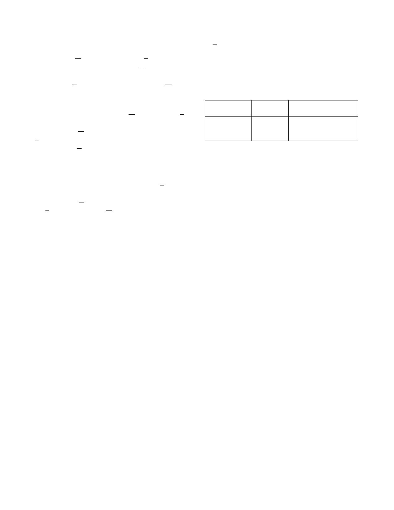
TYPICAL RADIATION HARDNESS
Table 2. Typical Radiation Hardness
Design Specifications1
Total Dose 50
krad(Si) nominal
Heavy Ion
Error Rate2
<1E-8
Errors/Bit-Day
Notes:
1. The SRAM will not latchup during radiation exposure under recommended
operating conditions.
2. 90% worst case particle environment, Geosynchronous orbit, 100 m ils of
Aluminum.
3
Share Link: 