LV4920H Ver la hoja de datos (PDF) - SANYO -> Panasonic
NĂșmero de pieza
componentes DescripciĂłn
Fabricante
LV4920H Datasheet PDF : 12 Pages
| |||
LV4920H
3.2 Thermal protection circuit
The thermal protection circuit detects the temperature (150°C or higher) inside the IC and protects the IC from
thermal damage. When the protection circuit is activated, both the high- and low-side output transistors are
turned off, placing the output into the high-impedance state. This protective operation is given a hysteresis.
Also, NOD_OUTSHDNB (Nch open drain) signal is output for an external monitor pin.
3.3 Low power supply voltage protection circuit
The low power supply voltage protection circuit turns off both of the high- and low-side output transistors to
place the output into the high-impedance state when the power supply voltage (PVD) falls below a predetermined
value (6.7V or lower). This operation (activating the protective circuit when VD rises beyond 7.5V) is given a
hysteresis (0.8V or greater).
Also, NOD_OUTSHDNB (Nch open drain) signal is output for an external monitor pin.
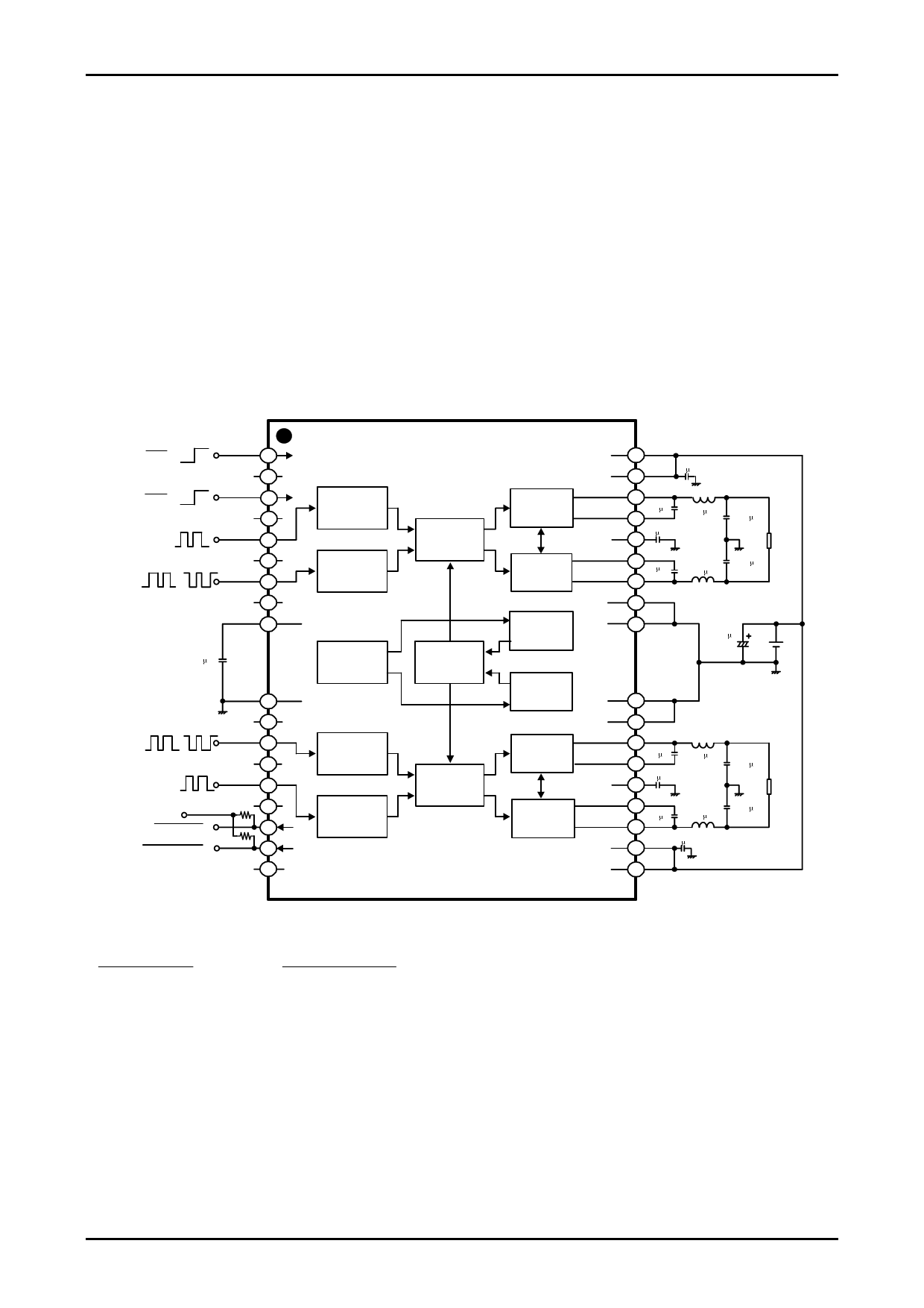
Application Circuit Example
0-5V
STBY
1
0-5V
MUTE
NC1 2
33
NC2 4
PWM_A1
45
NC3
PWM_B1
or
(BD-mode) (AD-mode)
NC4
46
47
48
VREG5
49
1F
LV4920H(HSOP36)
PVD1 36
PVD1 35
PWM_RECEIVER
PWM_RECEIVER
CONTROL
DELAY
OUT_CH1_P 34
OUTPUTSTAGE
CH1+
BOOT_CH1_P
33
0.1 F
VDDA1 32 1 F
BOOT_CH1_N
31
OUTPUTSTAGE
0.1 F
CH1-
OUT_CH1_N 30
PGND1 29
THERMAL
PGND1 28
1F
22 H
0.33 F
22 H
0.33 F
1000 F
RL
VD
POWER SUPPLY
SEQUENCE
140 GND
NC5 141
PWM_B2
or
142
(BD-mode) (AD-mode)
NC6 143
PWM_A2
144
3-12V
NOD_THERM
NOD_OUTSHDN
NC7 145
R1
146
R2 147
NC8 148
PWM_RECEIVER
PWM_RECEIVER
CONTROL
DELAY
OVER
CURRENT
PGND2 27
PGND2
26
OUTPUTSTAGE
CH2-
OUT_CH2_N 25
BOOT_CH2_N
24
0.1 F
VDDA2 23 1 F
22 H
OUTPUTSTAGE
CH2+
BOOT_CH2_P
22
OUT_CH2_P 21
0.1 F
22 H
PVD2 20
1F
PVD2 19
0.33 F
RL
0.33 F
R1,R2=Pull-Up Registor
* NOD_THERM at pin 16 and NOD_OUTSHDN at pin 17 are outputs of N-ch open-drain type. When CPU or other
device monitors these outputs, it is necessary to connect pull-up resistors to a power supply for the CPU and other
device. The pull-up resistors are not required if they are not to be used (not monitored).
No.A0989-10/12
Share Link: 