LV23000 Ver la hoja de datos (PDF) - SANYO -> Panasonic
Número de pieza
componentes Descripción
Fabricante
LV23000 Datasheet PDF : 14 Pages
| |||
LV23000M
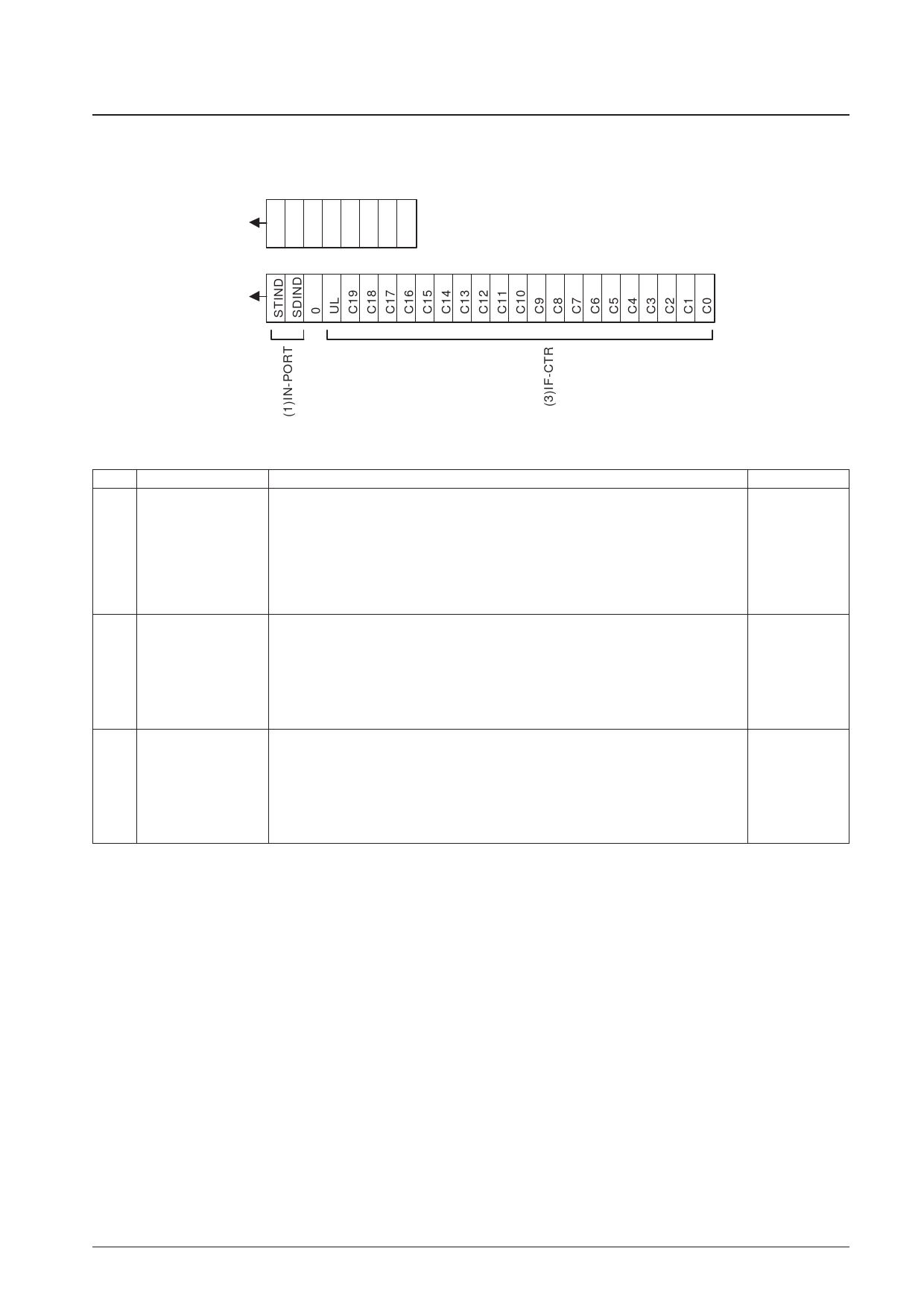
Structure of the DO Control Data (Serial Output Data)
(1) OUT mode
Address
DI
01010100
DO
DO Output Data
No.
Control block/data
Stereo indicator
SD indicator
(1)
Control data
STIND, SDIND
Description
• Indicates the states of the stereo and SD indicators at the point latched.
The data is latched at the point the devices goes to data output mode (OUT mode).
STIND ← Stereo indicator state: 0: ST on, 1: ST off
SDINC ← SD indicator state: 0: SD on, 1: SD off
PLL unlocked data
• Indicates the state of the unlock detection circuit at the point latched.
(2)
UL ← 0: Unlocked
UL
1: Locked or detection stopped mode.
IF counter
• Indicates the content of the IF counter (20-bit binary counter) at the point latched.
Binary counter
(3)
C19 ← MSB of the binary counter
C19 to C0
C0 ← LSB of the binary counter
Related data
UL0
UL1
CTE
GT0
GT1
No. 6903-8/14
Share Link: 