LTC4252-1IMS8-TRPBF Ver la hoja de datos (PDF) - Linear Technology
Número de pieza
componentes Descripción
Fabricante
LTC4252-1IMS8-TRPBF Datasheet PDF : 36 Pages
| |||
LTC4252-1/LTC4252-2
LTC4252A-1/LTC4252A-2
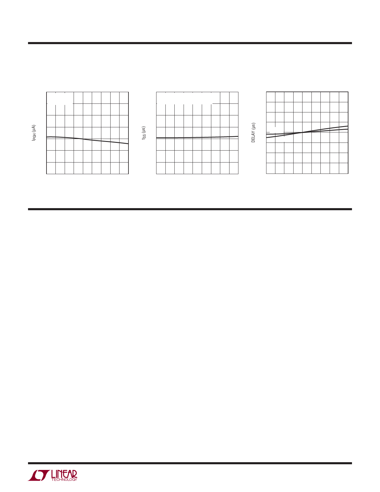
TYPICAL PERFORMANCE CHARACTERISTICS
IPGH vs Temperature
62
VPWRGD = 0V
61 (MS ONLY)
60
59
58
57
56
55
–55 –35 –15 5 25 45 65 85 105 125
TEMPERATURE (°C)
425212 G38
tSS vs Temperature
220
SS PIN FLOATING,
210 VSS RAMPS FROM 0.2V TO 2V
200
190
180
170
160
150
–55 –35 –15 5 25 45 65 85 105 125
TEMPERATURE (°C)
425212 G27
tPLLUG and tPHLOG
vs Temperature
0.8
0.7
0.6
0.5
0.4 tPLLUG
tPHLOG
0.3
0.2
0.1
0
–55 –35 –15 5 25 45 65 85 105 125
TEMPERATURE (°C)
425212 G24
PIN FUNCTIONS (MS/MS8)
VIN (Pin 1/Pin 1): Positive Supply Input. Connect this
pin to the positive side of the supply through a dropping
resistor. A shunt regulator clamps VIN at 13V. An internal
undervoltage lockout (UVLO) circuit holds GATE low until
the VIN pin is greater than VLKO, overriding UV and OV. If
UV is high, OV is low and VIN comes out of UVLO, TIMER
starts an initial timing cycle before initiating a GATE ramp-
up. If VIN drops below approximately 8.2V, GATE pulls low
immediately.
PWRGD (Pin 2/Not Available): Power Good Status Output
(MS only). At start-up, PWRGD latches low if DRAIN is
below 2.385V and GATE is within 2.8V of VIN. PWRGD
status is reset by UV, VIN (UVLO) or a circuit breaker fault
timeout. This pin is internally pulled high by a 58μA cur-
rent source.
SS (Pin 3/Pin 2): Soft-Start Pin. This pin is used to ramp
inrush current during start up, thereby effecting control
over di/dt. A 20x attenuated version of the SS pin voltage
is presented to the current limit amplifier. This attenuated
voltage limits the MOSFET’s drain current through the sense
resistor during the soft-start current limiting. At the begin-
ning of a start-up cycle, the SS capacitor (CSS) is ramped
by a 22μA (28μA for the LTC4252A) current source. The
GATE pin is held low until SS exceeds 20 • VOS = 0.2V.
SS is internally shunted by a 100k resistor (RSS) which
limits the SS pin voltage to 2.2V (50k resistor and 1.4V
for the LTC4252A). This corresponds to an analog current
limit SENSE voltage of 100mV (60mV for the LTC4252A). If
the SS capacitor is omitted, the SS pin ramps up in about
180μs. The SS pin is pulled low under any of the following
conditions: in UVLO, in an undervoltage condition, in an
overvoltage condition, during the initial timing cycle or
when the circuit breaker fault times out.
SENSE (Pin 4/Pin 3): Circuit Breaker/Current Limit Sense
Pin. Load current is monitored by a sense resistor RS con-
nected between SENSE and VEE, and controlled in three
steps. If SENSE exceeds VCB (50mV), the circuit breaker
comparator activates a (230μA + 8 • IDRN) TIMER pull-up
current. If SENSE exceeds VACL, the analog current limit
amplifier pulls GATE down to regulate the MOSFET current
at VACL/RS. In the event of a catastrophic short-circuit,
SENSE may overshoot. If SENSE reaches VFCL (200mV),
the fast current limit comparator pulls GATE low with a
strong pull-down. To disable the circuit breaker and cur-
rent limit functions, connect SENSE to VEE.
425212fd
9
Share Link: 