LTC1421 Ver la hoja de datos (PDF) - Linear Technology
Número de pieza
componentes Descripción
Fabricante
LTC1421 Datasheet PDF : 24 Pages
| |||
LTC1421/LTC1421-2.5
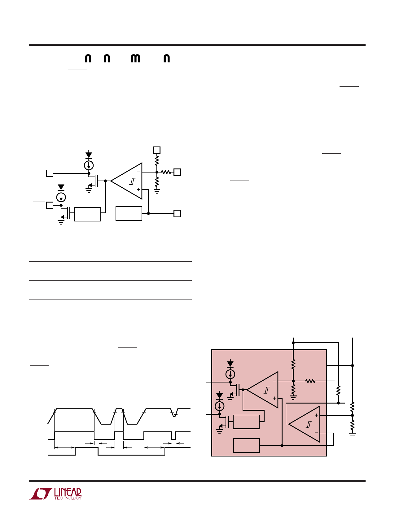
APPLICATIONS INFORMATION
PWRGD and RESET
The LTC1421 uses a 1.232V bandgap reference, internal
resistive divider and a precision voltage comparator to
monitor VOUTLO (Figure 6).
The reset threshold voltage for VOUTLO is determined by
the FB pin connection as summarized in Table 1.
PWRGD
VCCLO
VCCLO
20µA COMP1
VOUTLO
73.5k
71.5k
FB
26.7k
RESET
20µA
RESET
TIMING
1.232V
Figure 6. Supply Monitor Block Diagram
REF
1421 F06
Table 1
FEEDBACK PIN
Floating
VOUTLO
GND
VOUTLO RESET VOLTAGE
4.65V
2.90V
5.88V
When the VOUTLO voltage rises above its reset threshold
voltage, the comparator output goes low, and PWRGD is
immediately pulled high to VCCLO by a weak pull-up
current source or external resistor (Figure 7, time points
1 and 4). After a 200ms delay, RESET is pulled high. The
weak pull-up current source to VCCLO on PWRGD and
RESET have a series diode so the pins can be pulled above
VCCLO by an external pull-up resistor without forcing
current back into VCCLO.
1
V2
VOUTLO
2
3
4
V1 V2
V1 V2
5
V2 V1
PWRGD
RESET
32µs
200ms
< 200ms
<32µs
200ms
1421 F07
Figure 7. Power Monitor Waveforms
When VOUTLO drops below its reset threshold, the com-
parator output goes high, and PWRGD is immediately
pulled low (time point 2). After a 32µs delay, RESET is
pulled low. The RESET delay allows the PWRGD signal to
be used as an early warning that a reset is about to occur.
If the PWRGD signal is used as a interrupt input to a
microprocessor, a short power-down routine can be run
before the reset occurs.
If VOUTLO rises above the reset threshold for less than
200ms, the PWRGD output will trip, but the RESET output is
not affected (time point 3). If VOUTLO drops below the reset
threshold for less than 32µs, the PWRGD output will trip, but
again the RESET output will not be affected (time point 5).
Voltage Comparator
The uncommitted voltage comparator (COMP2) can be
used to monitor output voltages other than VOUTLO. Figure
8a shows how the comparator can be used to monitor a
12V supply (VOUTHI), while the 5V supply (VOUTLO) gener-
ates a reset when it dips below 4.65V. When the 12V
supply drops below 10.8V, COMPOUT will pull low. The FB
pin is left floating.
Figure 8b shows how the comparator can be used to
monitor the 5V supply (VOUTHI) while the 3.3V supply
(VOUTLO) generates a reset when it dips below 2.9V. When
the 5V supply drops below 4.65V, COMPOUT will pull low.
The FB pin is tied to VOUTLO.
5V
12V
VCCLO
6
VCCLO
20µA COMP1
20µA
7
RESET
TIMING
20
LTC1421
73.5k
16
71.5k
11
26.7k
15
COMP2
13
14
10k
5%
107k
1%
13.7k
1%
1.232V
8
1421 F08a
Figure 8a. Monitor 12V, Reset 5V at 4.65V
9
Share Link: 