LTC1421 Ver la hoja de datos (PDF) - Linear Technology
Número de pieza
componentes Descripción
Fabricante
LTC1421 Datasheet PDF : 24 Pages
| |||
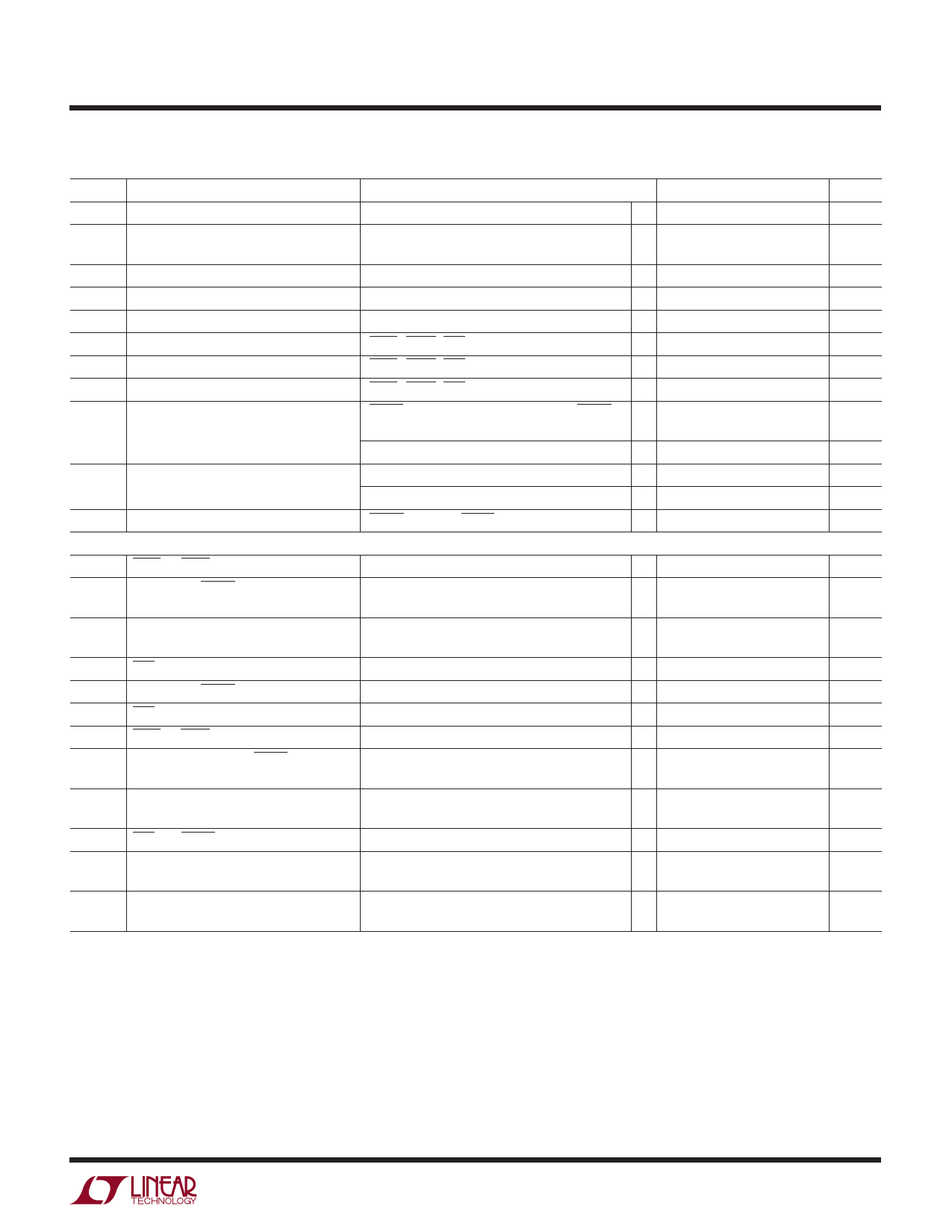
LTC1421/LTC1421-2.5
ELECTRICAL CHARACTERISTICS The q denotes specifications which apply over the full operating
temperature range, otherwise specifications are at TA = 25°C. VCCHI = 12V, VCCLO = 5V unless otherwise noted (Note 2).
SYMBOL PARAMETER
CONDITIONS
MIN TYP MAX
UNITS
IRAMP
ICP
RAMP Pin Output Current
Charge Pump Output Current
Charge Pump On, VRAMP = 0.4V
Charge Pump On, GATEHI = 0V
GATELO = 0V
q 11
17
23
µA
– 600
µA
– 300
µA
∆VGATEHI
∆VGATELO
VAUXVCC
VIL
VIH
IIN
VOL
GATEHI N-Channel Gate Drive
GATELO N-Channel Gate Drive
Auxiliary VCC Output Voltage
Input Low Voltage
Input High Voltage
Input Current
Output Low Voltage
VOH
Output High Voltage
IPU
Logic Output Pull-Up Current
AC CHARACTERISTICS
VGATEHI − VOUTHI
VGATELO − VOUTLO
VCCLO = 5V, Unloaded
CON1, CON2, POR
6
16
V
10
16
V
4.5
V
q
0.8
V
CON1, CON2, POR
q2
V
CON1, CON2, POR = GND
q – 30 – 60 – 90
µA
RESET, COMPOUT, PWRGD, DISABLE, FAULT, q
IO = 3mA
0.4
V
CPON, IO = 3mA
q
1.45
V
DISABLE, IO = – 3mA
q4
V
CPON, IO = – 1mA
q 3.4
V
RESET, PWRGD, FAULT = GND
– 15
µA
t1
CON1 or CON2↓ to CPON↑
t2
PWRGD↑ to RESET↑
Figure 1, CL = 15pF
Figure 1, RL = 10k to VCCLO, CL = 15pF
q 15
20
30
ms
160
200
240
ms
q 140 200 280
ms
t3
PWRGD↑ to DISABLE↓
Figure 1, CL = 15pF
160
200
240
ms
q 140 200 280
ms
t4
POR↓ to CPON↓
t5
PWRGD↓ to RESET↓
t6
POR↑ to CPON↑
t7
CON1 or CON2↑ to CPON↓
t9
Short-Circuit Detect to FAULT↓
t10
Short-Circuit Detect to CPON↓
t11
POR↑ to FAULT↑
tCHL
Comparator High to Low
tCLH
Comparator Low to High
Figure 1, CL = 15pF
Figure 1, RL = 10k to VCCLO, CL = 15pF
Figure 1, CL = 15pF
Figure 1, CL = 15pF
Figure 1, RL = 10k to VCCLO, CL = 15pF
VCCLO – SETLO = 0mV to 100mV
Figure 2, CL = 15pF
VCCLO – SETLO = 0mV to 100mV
Figure 2, RL = 10k to VCCLO, CL = 15pF
COMP – = 1.232V, 10mV Overdrive
RL = 10k to VCCLO, CL = 15pF
COMP – = 1.232V, 10mV Overdrive
RL = 10k to VCCLO, CL = 15pF
q 15
20
30
ms
32
µs
50
ns
50
ns
20
µs
20
µs
20
ns
q
0.25
0.5
µs
q
1
1.5
µs
Note 1: Absolute Maximum Ratings are those values beyond which the life
of a device may be impaired.
Note 2: All currents into device pins are positive; all currents out of device
pins are negative. All voltages are reference to ground unless otherwise
specified.
Note 3: After power-on reset, the VOUTLO and VOUTHI have to drop below the
VTRIP point before the charge pump is restarted.
Note 4: After power-on reset, the VOUTLO has to drop below the VTRIP point
before the charge pump is restarted.
3
Share Link: 