LTC1153 Ver la hoja de datos (PDF) - Linear Technology
Número de pieza
componentes Descripción
Fabricante
LTC1153 Datasheet PDF : 16 Pages
| |||
LTC1153
APPLICATI S I FOR ATIO
should be connected across the load, as shown in Figure
2, to safely divert the stored energy.
Using the values shown in Figure 3, the start-up current is
less than 100mA and does not false-trip the breaker.
Capacitive Loads
Large capacitive loads, such as complex electrical sys-
tems with large bypass capacitors, should be powered
using the circuit shown in Figure 3. The gate drive to the
power MOSFET switch is passed through an RC delay
network, R1 and C1, which greatly reduces the turn on
ramp rate of the switch. And since the MOSFET source
voltage follows the gate voltage, the load is powered
smoothly and slowly from ground. This dramatically re-
duces the start-up current flowing into the supply capaci-
tor/s which, in turn, reduces supply transients and allows
for slower activation of sensitive electrical loads. (Diode,
D1, provides a direct path for the LTC1153 protection
circuitry to quickly discharge the gate).
12V
IN
VS
CT
DS
CT
0.47µF
LTC1153
STATUS
G
GND
SD
+
CD
0.01µF
D1
1N4148
470µF
RD
1OOk
0.036Ω
R1
1OOk
R2
1OOk
C1
0.33µF
MTP3055E
15V
+
OUT
CLOAD
100µF
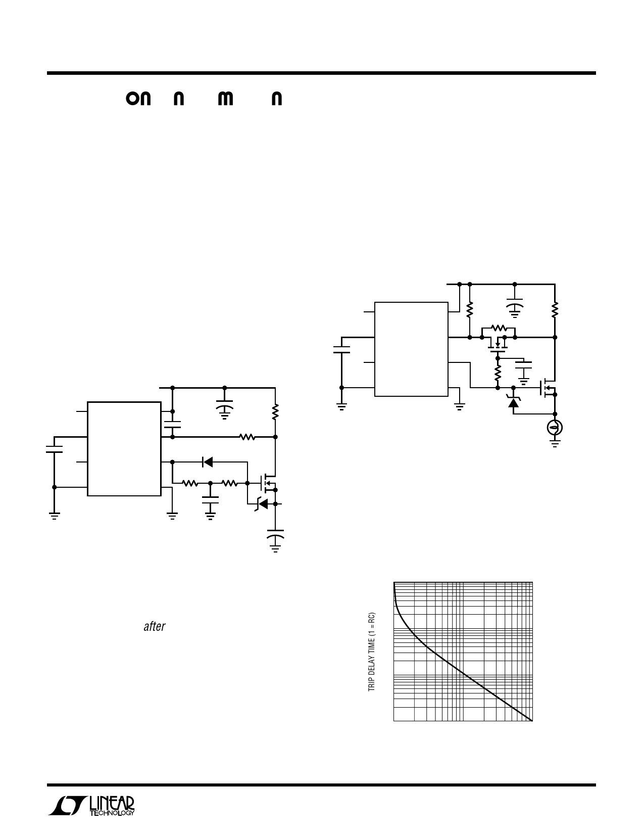
Figure 3. Powering Large Capacitive Loads
LTC1153 • F03
The RC network, RD and CD, in series with the drain sense
input should be set to trip based on the expected charac-
teristics of the load after start-up. With this circuit, it is
possible to power a large capacitive load and still react
quickly (10µs) to break the circuit if a short-circuit condi-
tion is encountered. The ramp rate at the output of the
switch as it lifts off ground is approximately:
dV/dt = (VGATE – VTH)/(R1 × C1)
And therefore the current flowing into the capacitor during
start-up is approximately:
ISTART-UP = CLOAD × dV/dt
Lamp Loads
The inrush current created by a lamp during turn-on can be
10 to 20 times greater than the rated operating current.
The circuit shown in Figure 4 shifts the trip threshold up by
a factor of 11:1 (to 30A) for 100ms while the bulb is turned
on. The trip threshold then drops down to 2.7A after the
inrush current has subsided.
12V
IN
VS
CT
DS
CT
0.33µF
LTC1153
STATUS
G
GND
SD
+
10k
100k
470µF
0.036Ω
VN2222LL
0.1µF
1M
MTP3055EL
9.1V
12V/1A
BULB
LTC1153 • F04
Figure 4. Lamp Driver with Delayed Protection
Selecting RD and CD
Figure 5 is a graph of normalized breaker trip time versus
breaker current. This graph is used to select the two delay
components, RD and CD, which make up a simple RC delay
between the drain sense resistor and the drain sense input.
10
1
0.1
0.01
1
10
100
BREAKER CURRENT (1 = SET CURRENT)
LTC1153 • F05
Figure 5. Trip Delay Time vs Breaker Current
9
Share Link: 