LT5528EUF Ver la hoja de datos (PDF) - Linear Technology
Número de pieza
componentes Descripción
Fabricante
LT5528EUF Datasheet PDF : 16 Pages
| |||
LT5528
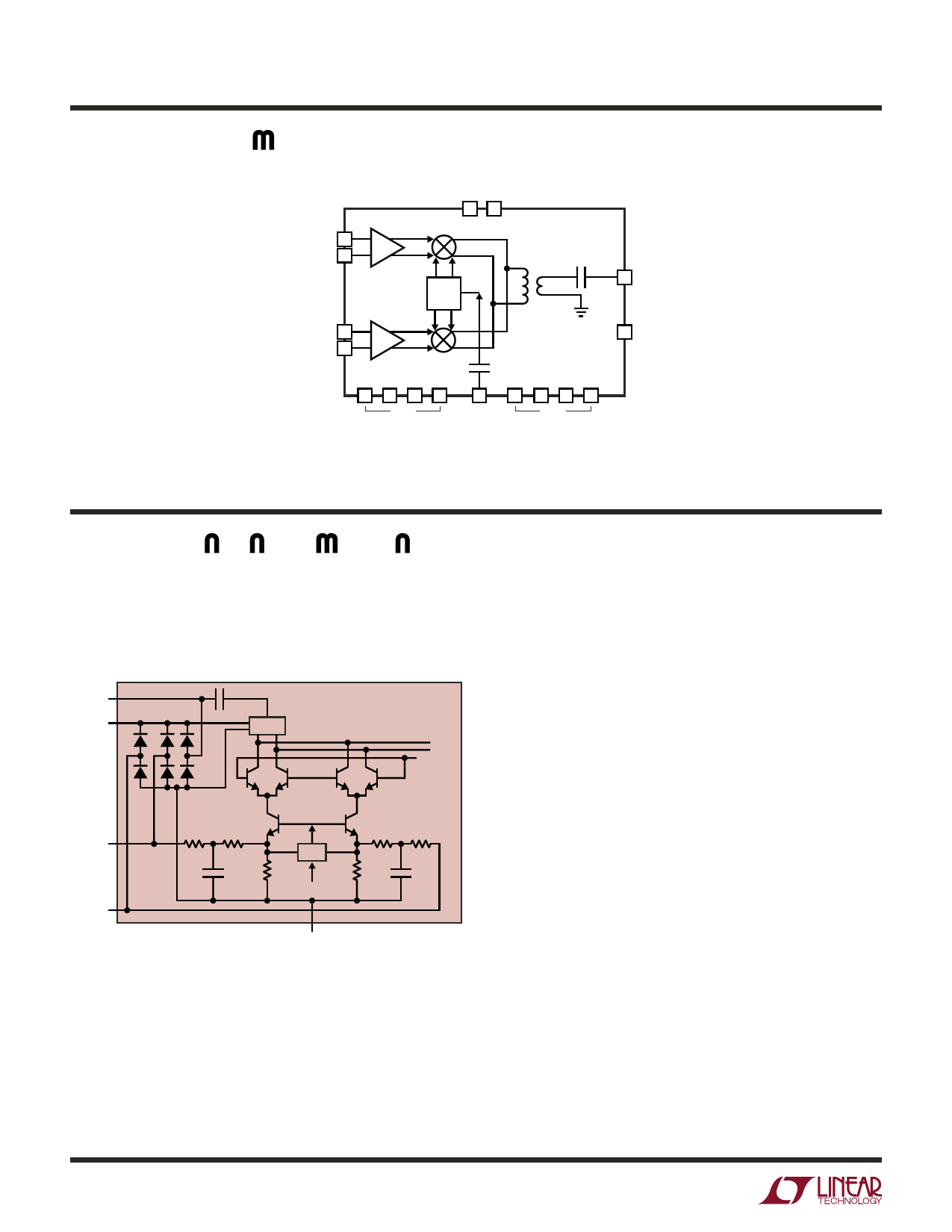
BLOCK DIAGRA
BBPI 14
V-I
BBMI 16
BBPQ 7
V-I
BBMQ 5
VCC
8 13
LT5528
0°
90°
BALUN
11 RF
1 EN
2469
GND
3
10 12 15 17
5528 BD
LO
GND
APPLICATIO S I FOR ATIO
The LT5528 consists of I and Q input differential voltage-
to-current converters, I and Q up-conversion mixers, an
RF output balun, an LO quadrature phase generator and
LO buffers.
RF
VCC = 5V
C
BALUN
LOMI
LT5528
FROM
Q
LOPI
R1A R1B
R2B R2A
20Ω 23Ω
23Ω 20Ω
BBPI
CM
12pF
R3
R4
12pF
VREF = 0.52V
BBMI
GND
5528 F01
Figure 1. Simplified Circuit Schematic of the LT5528
(Only I-Half is Drawn)
External I and Q baseband signals are applied to the dif-
ferential baseband input pins, BBPI, BBMI, and BBPQ,
BBMQ. These voltage signals are converted to currents and
translated to RF frequency by means of double-balanced
up-converting mixers. The mixer outputs are combined
in an RF output balun, which also transforms the output
impedance to 50Ω. The center frequency of the resulting
RF signal is equal to the LO signal frequency. The LO input
drives a phase shifter which splits the LO signal into in-
phase and quadrature LO signals. These LO signals are then
applied to on-chip buffers which drive the up-conversion
mixers. Both the LO input and RF output are single-ended,
50Ω-matched and AC coupled.
Baseband Interface
The baseband inputs (BBPI, BBMI), (BBPQ, BBMQ) present
a differential input impedance of about 90Ω. At each of the
four baseband inputs, a first-order low-pass filter using 20Ω
5528f
8
Share Link: 