LT5526EUF Ver la hoja de datos (PDF) - Linear Technology
Número de pieza
componentes Descripción
Fabricante
LT5526EUF Datasheet PDF : 16 Pages
| |||
LT5526
APPLICATIO S I FOR ATIO
The external inductance is split in half (1.4nH), with each
half connected between the pin and C1 as shown in
Figure 4. The inductance may be realized with short, high
impedance printed transmission lines, as in Figure 3,
which provides a compact board layout and reduced
component count. A 1:1 transformer (T1 in Figure 3)
converts the 50Ω differential impedance to a 50Ω single-
ended input.
1/2 XEXT
RF+ 1/2 XRF
2
LT5526
RS
50Ω
C1
1/2 XEXT
RF– 1/2 XRF
RRF
3
5526 F04
Figure 4. RF Input Impedance Matching Topology
Table 1. RF Input Differential Impedance
FREQUENCY
(MHz)
INPUT
IMPEDANCE
REFLECTION COEFFICIENT
MAG
ANGLE
70
28.0 + j1.34
0.282
176
140
28.2 + j2.46
0.280
172
240
28.4 + j3.30
0.278
169
360
28.4 + j4.75
0.282
164
450
28.6 + j5.42
0.280
162
750
29.9 + j7.39
0.268
155
900
31.3 + j8.41
0.251
150
1500
38.3 + j17.9
0.237
112
1900
42.5 + j24.6
0.269
92.2
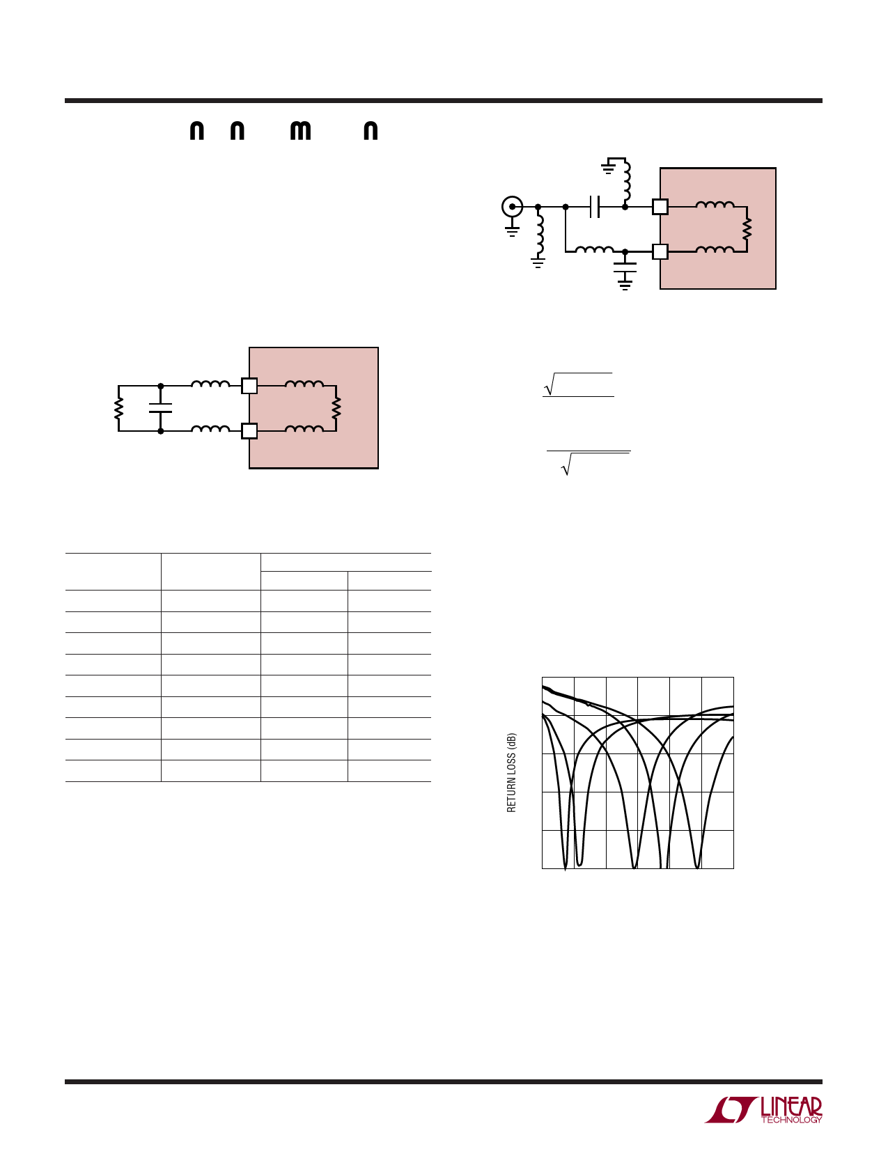
An alternative method of driving the RF input is to use a
lumped-element balun configuration, as shown in Fig-
ure 5. This type of network may provide a more cost-
effective solution for narrow band applications (fractional
bandwidths < 30%). The actual balun is composed of
components C7, C9, L1 and L4, and their values may be
estimated as follows:
RFIN
50Ω
C7
L1
LT5526
RF+ 1/2 XRF
2
L5
L4
RF– 1/2 XRF
RRF
3
C9
5526 F05
Figure 5. Schematic of Lumped Element Input Balun
L1= L4 = RS • RRF
ω
C7 = C9 =
1
ω RS • RRF
Where RS is the source resistance (50Ω) and RRF is the
mixer input resistance from Table 1.
The computed values are only approximate, as they don’t
factor in the effects of XRF or the parasitics of the external
components. Actual component values for several fre-
quencies are listed in Table 2, and measured return loss
vs. frequency is plotted for each example in Figure 6.
0
–5
–10
–15
–20
–25
100 300 500 700 900 1100 1300
FREQUENCY (MHz)
5526 F06
Figure 6. Input Return Loss with Lumped Element Baluns
Using Values from Table 2
5526f
10
Share Link: 